Robotics, stereo vision and lidar for lunar exploration
- 1Ecole de l'air, University AIX-MARSEILLE, Salon de Provence, France (thomas.aymeric@ecole-air.fr)
- 2Ecole de l'air, University AIX-MARSEILLE, Salon de Provence, France (ugo.cesari@ecole-air.fr)
- 3ESA / ESTEC, ILEWG & Leiden/VUA, SCI-S, bernard.Foing@esa.int
Among several other projects, to enable a manned space mission to the Moon or Mars, the rovers that will be sent there, as precursors, need to have 3D environment mapping tools. Thanks to them, we will be able to choose the ideal location to build a viable habitat for the future missions. To perform a mapping, there are several techniques. These must be able to work in extreme conditions, like on the Moon in space, where there is no atmosphere or in more mild conditions like Martian atmosphere (7 mbar). In addition, they must not generate heavy digital data to be transmitted to Earth for analysis. Our choice fell on two known techniques, which are relatively quick to use and which comply with the recommendations listed above: LiDAR (Light Detection And Ranging) and 3D stereophotogrammetry. The objective of our thesis was to compare these two 3D tools and to find a suitable mobile platform. This comparison was made by following a protocol that evaluated its techniques on their precision, their resolution and distance measurement compared to the same scene captured under the same initial conditions.
First of all, the equipment used for the rover are quite simple but will provide a basic platform:
- Caterpillar type transmission.
- 2 DC Motors.
- 3,000 mAh battery.
- Microcontroller: Raspberry Pi3.
- Board extension for the actuators.
- Pan tilt.
- Camera sensor.
There are three main programs for the rover’s control.
- VNC Viewer for the remote control of the SBC.
- Python for the control of the actuator.
- Motion for the display of the video sensor.
Then, we are going to explain what equipment we used to perform the tests. In order to create a LiDAR 3D scanner, we used:
- Sensor: TFmini from Benewake.
- 2 Servomotors (azimuth/elevation): type SG 90.
- Pan tilt.
- Microcontroller: Raspberry Pi 3B.
- Power supply: 20,000 mAh.
- Python: to create an algorithm.
- Software: Matlab (academic version), Meshlab (open source) and VNC viewer for remote control.
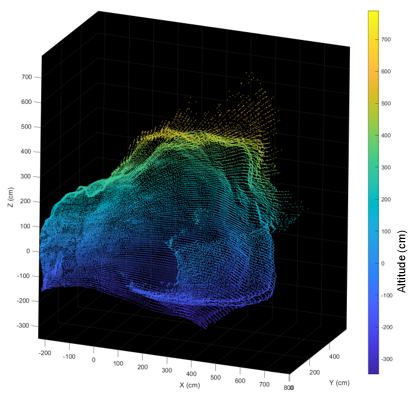
Its resolution is 0.5° in azimuth and elevation. Once the mapping of the rover’s surroundings is complete, the scanner saves a csv file with x, y, z coordinates with which we can generate a point cloud in Matlab (Fig.1) or Meshlab.


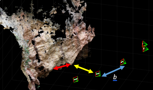
Fig.1: A cave mapped by a lidar 3D scanner. Fig.2: A cave 3D reconstructed using stereophotogrammetry with MicMac software.
For stereophotogrammetry, we used:
- Sensor: camera Fujifilm X-M1 (resolution 4896x3264, FoV: 83°, f=16mm) and webcam Logitech C920 HD Pro (resolution 1920x1080, FoV: 60°).
- Checkboard: needed for calibration, it is not mandatory but highly recommended for the accuracy.
- Software: Micmac (open source provided by French National Geographic Institute) or Matlab (academic version).
Pictures (from 2 to 5) were taken with a random basis b (Fig.2). Furthermore, we needed to know the distance between the camera and a known point in the scene (yellow arrow Fig.2) and a distance between two known points on the scene (red arrow Fig.2) to make the comparison. We did the same protocol with the lidar 3D scanner.
In order to have good results, we need to follow a protocol to obtain exploitable images for stereophotogrammetry. This protocol breaks down into different parts:
- Lighting: the light must be sufficient, constant, and uniform, that’s why the use of flash is prohibited
- Camera settings: pictures must be made with constant parameters, allowing their sharpness, correct exposure, and sufficient definition.
- Lens: focal length must remain the same throughout the acquisition.
- White balance: fixed for all picture in the series.
- Sensitivity: as a rule, avoid going up in ISO.
- Aperture: choose an opening small enough for the entire object to be clear.
- Shutter speed: it should be adjusted to allow proper exposure.
- Save images: in RAW or JPEG (maximum quality) and disable automatic image rotation.
- Image processing: all images must be developed with the same parameters. Check the images before putting them on the platform and always delete those that are blurred. Never crop an image, sometimes this manipulation deletes exif data.
In stereophotogrammetry, we faced one problem, only with the webcam that we used. The software needed some exif data about an image like the focal length used to capture it or the equivalent focal length assuming a 35mm film camera and the webcam did not put any information in the exif. We were able to solve this problem by making a calibration via Matlab software using a checkboard that provide us the intrinsic and extrinsic webcam parameters.
Our progress led us to the following conclusions. First, the stereophotogrammetry is faster than LiDAR even including post processing. Without latency, you can obtain pictures very quickly while LiDAR needs at least 25 minutes with our algorithm to map the rover surroundings. The second point is that LiDAR can map more space from just one position while with stereophotogrammetry you need to move the rover in several points to improve the resolution and accuracy of your 3D reconstruction. That is an important issue because the rover’s movements could be restricted.
However, for best results we can merge the two point clouds from lidar and stereophotogrammetry to obtain the accuracy of lidar and the realism of stereophotogrammetry.
The point of view of the rover camera is distorted by the lack of references of sizes and distances. One simple way to reduce this is to place a pattern in the visual field of the camera. That way the teleoperator will know if the rover can access difficult areas because he will see the future footprint of his rover. A more active way is to measure the range of targets by using Lidar. The restricted point of view of the operator can be compensate by multiple mobile cameras. In fact, multiple cameras can enhance greatly the comfort of the user. Larger field of vision of the user means less stress. Specific cameras can be used for operations (night vision, 360° recording). Installing multiple cameras is not limited to the user comfort, it can also be used by stereophotogrammetry. Indeed, we can add a camera with well-known parameters that will be able to map the field in real-time if we accept reduced information.
How to cite: Aymeric, T., Cesari, U., and Foing, B.: Robotics, stereo vision and lidar for lunar exploration, Europlanet Science Congress 2020, online, 21 September–9 Oct 2020, EPSC2020-897, https://doi.org/10.5194/epsc2020-897, 2020

