
 1,2,2,
- 1Royal Holloway, University of London, United Kingdom (poppy.mcvann@rhul.ac.uk)
- 2Imperial College London, United Kingdom
- 3University of Stirling, Scotland
Introduction: Polarimetric analysis of SAR imagery can provide extensive information about the scattering properties of an imaged surface. When looking at the Lunar South Pole, where the presence and abundance of ice has been debated for decades [1][2], having in-depth information about the present scattering mechanisms is invaluable. The Dual Frequency SAR (DFSAR) onboard ISRO’s Chandrayaan-2 provides fully polarimetric data in both L- and S-band, with the former expected to be able to penetrate up to 5m in dry, low loss soils [3]. With most of the subsurface ice expected to be located within the Permanently Shadowed Regions (PSR) of craters, the high-resolution coverage of these regions provided by Chandrayaan-2 allows the areas to be studied in greater detail.
Study Region: Two craters, Kocher and Wiechert E, were selected for this study due to their anomalous nature – this meaning that the Circular Polarisation Ratio (CPR) of the crater is higher in the interior [4]. They both exhibit high backscatter returns around their rims, contain a PSR and have average temperatures lower than 100K. With Kocher having a diameter of >20km and Wiechert E having a diameter of <20km, their floor texture is an unusual characteristic, as often craters with a diameter greater than 20km are more complex and have features such as central peaks [5]. The radar-bright regions of the crater walls are a possible indicator of unique surface or subsurface materials.
Methodology: Utilising bespoke code developed in python to detect and then radiometrically calibrate each polarisation to beta0 (HH, HV, VH, VV) as a baseline visualization, further code is used to extract the Coherency (T) matrix [6] and Pauli vectors to begin polarimetric analysis. Where H represents horizontal and V represents vertical, the Pauli vector k is defined by

This base-level decomposition can be utilised to differentiate between surface scattering from the first matrix component SHH + SVV, dihedral structure scattering from the matrix component SHH – SVV, and volumetric scattering with the final matrix component 2SVH.
Another technique used for in-depth analysis of the surface scattering mechanisms is the Claude-Pottier decomposition: a second-order optimisation method for distributed targets that provides information on the randomness of the scattering mechanism (entropy) and the potential dominant component. The scattering components of the Cloud-Pottier decomposition are derived from the 3x3 [T] matrix.
Initial Results: Kocher crater can be seen in Fig. 2, with the hummocky textured floor and large PSR represented in blue. The bright radar return from the western wall could be due to wavelength sized scatterers within the crater wall, but equally it is common for sloped terrain perpendicular to the look angle of the radar to appear bright. Since the Pauli Decomposition has high-level links to the physical scattering mechanism, we can map its components in colours (see Fig. 1b): the volumetric scattering is represented in green, while the surface scattering seen across most of the swath is represented in blue. The volumetric scattering component from natural mediascould be a representation of either subsurface ice suspended within the regolith or crustal material, or other wavelength sized scatterers such as larger rocks mixed into the Lunar regolith. Further analysis utilising the Claude-Pottier code to constrain the origin of the scattering mechanisms is being undertaken – including the possibility of distributed subsurface ice.
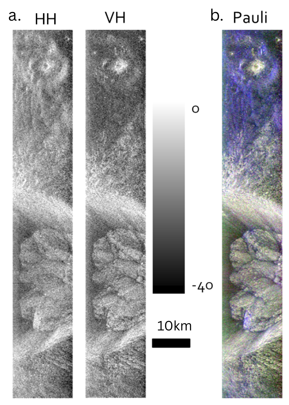
Fig. 1. (a) 5x5 Lee filtered HH and VH swath surrounding Kocher Crater (b) Pauli Decomposition of swath surrounding Kocher Crater.
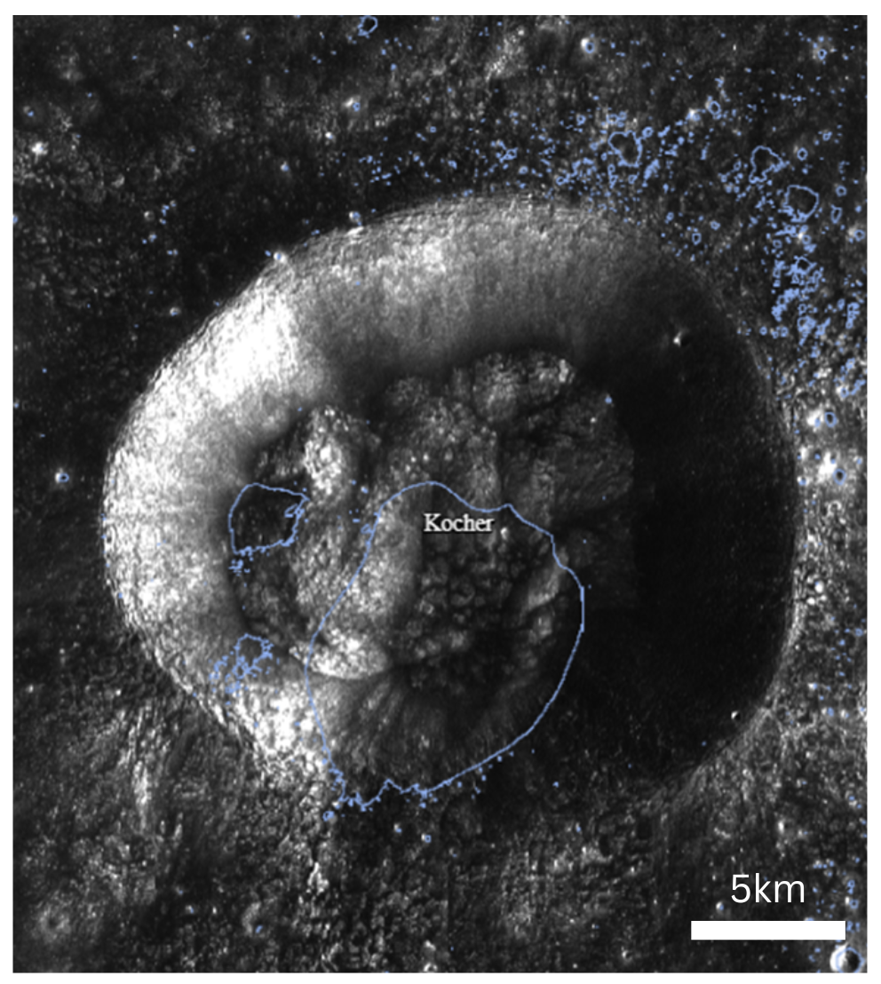
Fig. 2. West-looking S-band image from LRO Mini-RF of Kocher. The outlined blue areas are the PSR. Image taken using LROC Quickmap.
Future Plans: A deeper investigation integrating the results from different decompositions and the backscatter of all polarisation channels is aimed to be completed for the surrounding areas of each crater. The plan is to then mosaic the swaths together once projected onto the ground and create full images of each crater for a complete study.
When completed, the code used for this project is planned to be released.
With NASA’s Artemis III mission landing areas planned to be around the South Pole, and many other space agencies and commercial companies sending missions to this region, understanding the geological context of the area is key to success, in particular the presence and accessibility of water ice.
Acknowledgments: We acknowledge the use of data from the Chandrayaan-II, second lunar mission of the Indian Space Research Organisation (ISRO), archived at the Indian Space Science Data Centre (ISSDC). UK Space Agency for funding this project; grant no. ST/Y005384/1 as part of the UK Government’s Science Bilateral Programme. LROC Quickmap team for hosting datasets and the map.
References: [1] Watson K. et al. (1961) J. Geophysical Research, 66, 9. [2] Campbell D. B. et al. (2006) Nature, 443, 835-837. [3] Bhiravarasu S. S. et al. (2021) Planet. Sci. J., 2, 134. [4] Spudis P. D. et al. (2013) JGR Planets, 118, 10. [5] French, B. M. (1998). LPI Cont. No 954, pp. 27. [6] Lee J. S. and Pottier E. (2017) CRC press.
How to cite: McVann, P., Ghail, R., Gallardo i Peres, G., Mason, P., Marino, A., and Knight, C.: Polarimetric Analysis of Anomalous Lunar South Pole Craters from Chandrayaan-2 DFSAR Data, EPSC-DPS Joint Meeting 2025, Helsinki, Finland, 7–13 Sep 2025, EPSC-DPS2025-1701, https://doi.org/10.5194/epsc-dps2025-1701, 2025.