A unique lunar gas extraction event as part of the ANGSA Program and the lessons learned for a new generation of sample return missions
- 1European Space Agency, HRE, Netherlands (francesca.mcdonald@esa.int)
- 2ESA SSEAC, Cologne, Germany
- 3NASA Johnson Space Centre, Houston, USA
- 4Dept of Earth & Planetary Science and Dept. of Physics, Washington University in St. Louis, USA
- 5Institute of Meteoritics, University of New Mexico, USA
- 6ANGSA Science Team, https://www.lpi.usra.edu/ANGSA/teams/
Introduction: Apollo planned for the future, retaining a suite of specially curated pristine samples. One of these samples is an Apollo 17 double drive-tube core (73001/73002) [1], which samples down to 70 cm below the lunar surface within the ‘light mantle’ unit in the Taurus Littrow Valley (TLV) [2]. Models estimate a low temperature of ~250 K [3] at this depth, conducive for cold-trapping of volatiles. The lower core segment (73001) has been kept within a Core Sample Vacuum Container (CSVC) since 1972 when it was sealed under vacuum at the surface of the Moon [4]. On Earth, CSVC 73001 was sealed in a secondary outer vacuum container (OVC) at a pressure of ~6×10⁻² mbar [5]. One of the science goals for Apollo 17 was to target samples that may have trapped gases released from the lunar interior via the Lee-Lincoln fault [1]. The vacuum sealed CSVC 73001 presents a prime opportunity to investigate for such gases. Here we present the preparation and execution of a unique gas extraction event of CSVC 73001, as part of the Apollo Next Generation Sample Analyses (ANGSA) Program. This activity was led by an ANGSA subteam including the European Space Agency (ESA), Washington University St Louis (WUStL), JSC Apollo Sample Curation Facility and University of New Mexico (UNM).
Gas Extraction Set-Up & Challenges: A gas extraction set-up was created composed of two main hardware components: a piercing tool, designed and built by ESA, which interfaces with an ultra-high vacuum (UHV, order of pressure, ×10-9 mbar) gas extraction manifold developed and built by WUStL [6]. Technical and scientific challenges for the hardware design include: preserving the pristinity of the regolith and sample gases, avoiding contamination, preventing isotopic fractionation, capability to operate under UHV; accounting for limitations of dexterity when working within a dry N2 glovebox, and delivering on precision piercing of the CSVC stainless steel base without piercing the Teflon cap of the sample holder within.
Design and Manufacture: Following a hardware literature review [e.g., 4,7], an ‘agile’ iterative design approach was undertaken. This included: deriving a set of design requirements based on science, curation and technical needs; experimentally deriving the required piercing force and piercing tip dimension; iterative breadboarding; and regular consultation with ANGSA team members. The piercing tool was machined and manufactured at ESA and the extraction manifold built and calibrated at WUStL. Mechanical testing of the piercing tool under ambient conditions aided operational refinement and piercing tip calibration. Subsequent extensive testing under UHV demonstrated efficient, repeatable use of the piercing tool in meeting the objectives and identified challenges and requirements. The tested hardware underwent stringent cleaning and baking (heated in a vacuum oven at 180ºC for 72 hours) prior to being installed at JSC.
Outer Vacuum Container Gas Extraction: The OVC containing the CSVC and constituent sample was interfaced directly with the gas extraction manifold and a ‘blank’ sample of the background collected under UHV (order of ×10-9 mbar). A 100 cc ‘test’ aliquot and two gas samples were sequentially collected of the OVC gas, each for a duration of 15 minutes. The OVC gas could be important, if the CSVC may have leaked over the past 50 years. Initial (uncalibrated for system volume) pressures of the OVC sample (order of ×10-2 mbar) are consistent with that of the OVC when it was originally sealed.
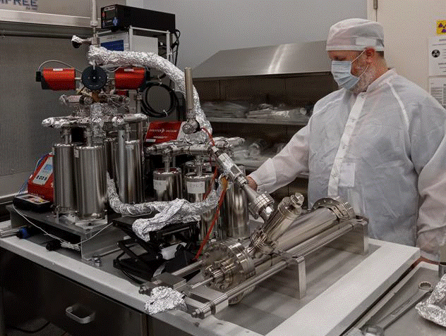
Piercing the CSVC: The CSVC was extracted from the OVC and rendered XCT images showed the most challenging scenario of the sample holder with the Teflon cap in direct contact with the CSVC base. The CSVC was transferred to the piercing tool and interfaced with the gas extraction manifold (Fig.1). Extensive He-leak testing indicated no atmospheric leaks. Monitoring of pressures and RGA spectra (using a quadrupole mass spectrometer) indicated that the CSVC may be leaking. The manifold was isolated with the system pressure at 8.7×10⁻⁹ mbar and the piercing commenced. A satisfying ‘pop’ marked successful piercing of the CSVC base. Test aliquots (100 cc); two ‘short’ 15 minute duration samples (uncalibrated pressure, ~6 mbar) and ‘long’ extraction (~1-2 week duration) samples were collected. Pressures and RGA spectra were monitored throughout from which a set of hypotheses on how well the OVC and the CSVC have performed have been made and will be tested as part of laboratory analyses of the gas. Analyses include determining general gas composition (Z. Sharp at UNM) and noble gas isotope ratios (R. Parai at WUStL). In particular, 20Ne/22Ne and 128Xe/130Xe can assess for presence of lunar gas [8].
Findings and Lessons Learned: The full performance of the piercing tool and CSVC is still to be fully assessed. First XCT and optical images of the CSVC base indicate a high-level of tool performance in terms of not having pierced the Teflon cap and producing an adequate size of hole. A baseline set of requirements and sequence of events have been demonstrated for a gas extraction procedure, which is informing a new generation of (volatile-rich) sample return missions (e.g., Artemis; Mars Sample Return). Synthesis of the CSVC performance will also inform development of easy to use containers with longer lasting, contaminant-free seals.
Other lessons learned include recommendations to: produce physical duplicates and digital twins of flight hardware; further research into hardware degradation during flight and with time; ensure early definition of mission goals and consultation with science teams and curators (critical for providing clear driving requirements for hardware development); include flexibility in sample container designs and interfaces that account for the entire return sample life-time needs and not just at point of collection.

Figure 1: Gas extraction setup composed of an UHV manifold and piercing tool.
References: [1] Meyer C. (2011) Lunar Sample Compendium. [2] Schmitt et al. (2017) Icarus, 298, 2-33. [3] Keimh S.J. and Langseth M.G. (1973) Proc. 4th Lunar Sci. Conf. 2503-2513. [4] Allton J.A. (1989) JSC23454, NASA. [5] Butler P. (1973) Lunar Sample Info. Catalog, NASA JSC. [6] Parai. R et al. (2021) LPSC LII, Abs #2665. [7] NASA JSC (1971) CSVC Technical Drawing, M-11306. [8] Curran, N.M. et al. (2020) PSS, 182, 104823.
How to cite: McDonald, F., Schild, T., Bamsey, N., Apolloni, M., Biella, R., Butenko, Y., Dowson, A., Eckley, S., Gross, J., Jolliff, B., Lindner, R., Makaya, A., McCubbin, F., Meshik, A., Parai, R., Pravdivtseva, O., Sharp, Z., Shearer, C., Zeigler, R., and Science Team, A.: A unique lunar gas extraction event as part of the ANGSA Program and the lessons learned for a new generation of sample return missions, Europlanet Science Congress 2022, Granada, Spain, 18–23 Sep 2022, EPSC2022-1117, https://doi.org/10.5194/epsc2022-1117, 2022.

