
Calibration of RDS of Mars 2020 and SIS’22 of Exomars 2022 for Mars exploration
 1,1,1,1
- 1National Institute of Aerospace Technique (INTA), Spain
- 2Ingeniería de Sistemas para la Defensa de España S.A (as an external consultant at INTA), Spain.
- 3Escribano Mechanical and Engineering S.L, Spain
Introduction
INTA Payloads and Space Science Department is involved in several scientific missions to Mars, developing solar irradiance sensors (SIS), name given for these devices which are multispectral multichannel radiometers for atmosphere studies.
Two SIS were manufactured before 2015: MetSIS (a radiometer intended to be launched onboard the for the Mars MetNet Precurssor Penetrator [1]) and the DREAMS-SIS for the ill-fated Shiaparelli lander of the ExoMars’16 mission ([2]-[5])
Two radiometers have been developed recently: the Radiation and Dust Sensor(RDS) for Mars2020 Perseverance ([6]-[7]) and the SIS'22 for Exomars 2022 Kazachok lander [8]. RDS is currently working on Mars [9]-[10].
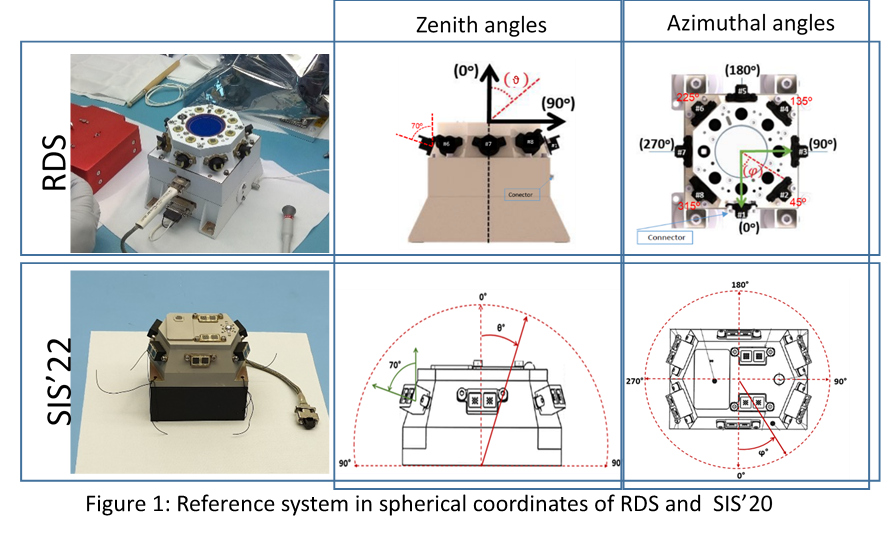
Either RDS and SIS’22 combine optical detectors which point to the zenith (top channels) and to the horizon, with an elevation of 20 degrees respect to the horizontality, and distributed in the azimuth (lateral channels).

Innovation
The optical response can be expressed with the following expression, which accounts for the mathematical model used in their calibration [11] and [13] to [19]:

This equation has four parameters:
- ARF, Angular Response Function. This term represents the influence on the channel response of the angular coordinates of the light source respect to every optical detector
- TRF, Thermal Response Function. It deals with the effect of the detector temperature in its response to a luminous source
- R, responsivity or mean throughput of the optical detector in the range between the wavelengths l1 and l2, to which the channel is sensitive.
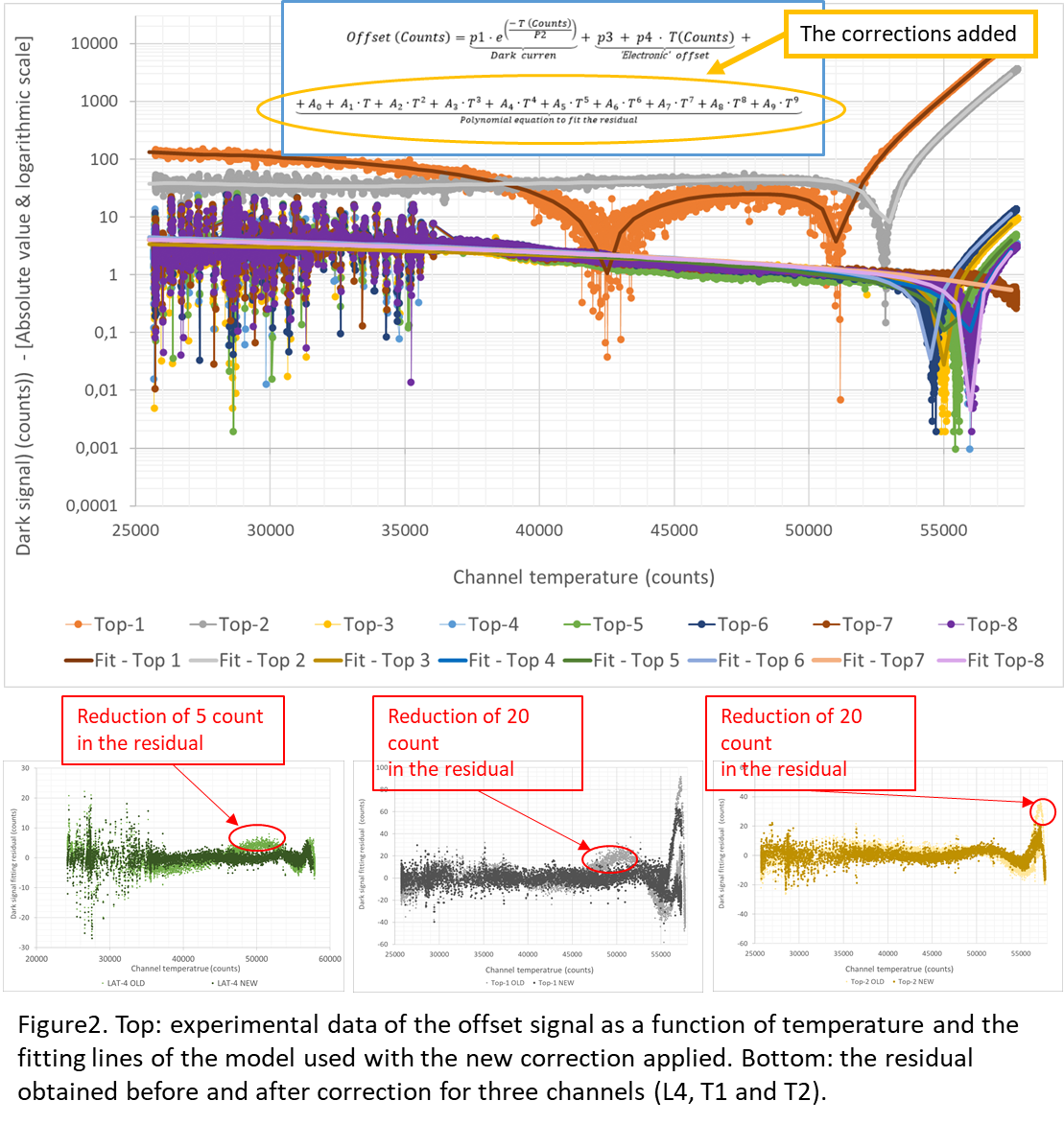
- Offset, related to the signal of the photodetectors in dark conditions and to the effects on the conditioning electronics on the signal level.
The model works under the assumption that angle, temperature, responsivity are independent variables [11]. Hence, four independent characterizations are run in order to get these four parameters:
- Offset calibration: In dark conditions, the temperature is swept to cover the entire thermal range.
- Optical Thermal calibration (TRF): the optical power and the angle of incidence of the light are fixed and only the temperature is made to change.
- Angular calibration (ARF): the optical power and the temperature are fixed and only the light incidence angle is made to change.
- Mean throughput measurement (RSun): the optical power lamp is excited in several steps, increasing irradiance from a low level to a high one at room temperature with the light at normal incidence over each optical channel.
Some of the changes had to be introduced for RDS and SIS’22 calibrations, as new challenges had to be overcome respect to the requirements imposed on the DREAMS SIS. These additional demands had an important impact on the calibration:
- Narrower FoVs. The alignment is more critical and a new ARF model was implemented.
- UV channels: different light sources, with a higher signal in the UV, were used.
- Some channels were designed to detect only diffuse light: light intensity of the solar simulation had to be reduced drastically for the particular calibration of those channels.
- Having six and eight lateral channels instead of three entailed a higher complexity in the angular sweep and mean throughput alignment.
In the particular case of the RDS, having completed the calibration and field campaigns in representative Martian analogous, the first measurements obtained directly from Mars showed some mismatches with the calibration model. A refinement of the analyses was performed to reduce these discrepancies and to improve the lowest measurable signal level:
- Corrections were introduced in the offset model in order to reduce the discrepancy between the experimental points and the fitting (the residual) by up to 20 counts at a full scale of 65535 (0.05%). That becomes essential in very low light conditions and certain temperatures. It can be as much as a 50 % of the signal. However, such temperatures have never been reached in RDS and even less at times of low illumination (sunrise or sunset).
- A spectral correction below 2 % was introduced to calculate the mean responsivity of the sun simulator. This lamp source produces a spectrum which is very similar to that of the sun outside the atmosphere. A correction to fit its radiance to a perfect solar spectrum had not been used before.
- The main upgrade comes from the modelization of the ARF, its “blocking zone” and the effects of the dust in Mars.
ARF
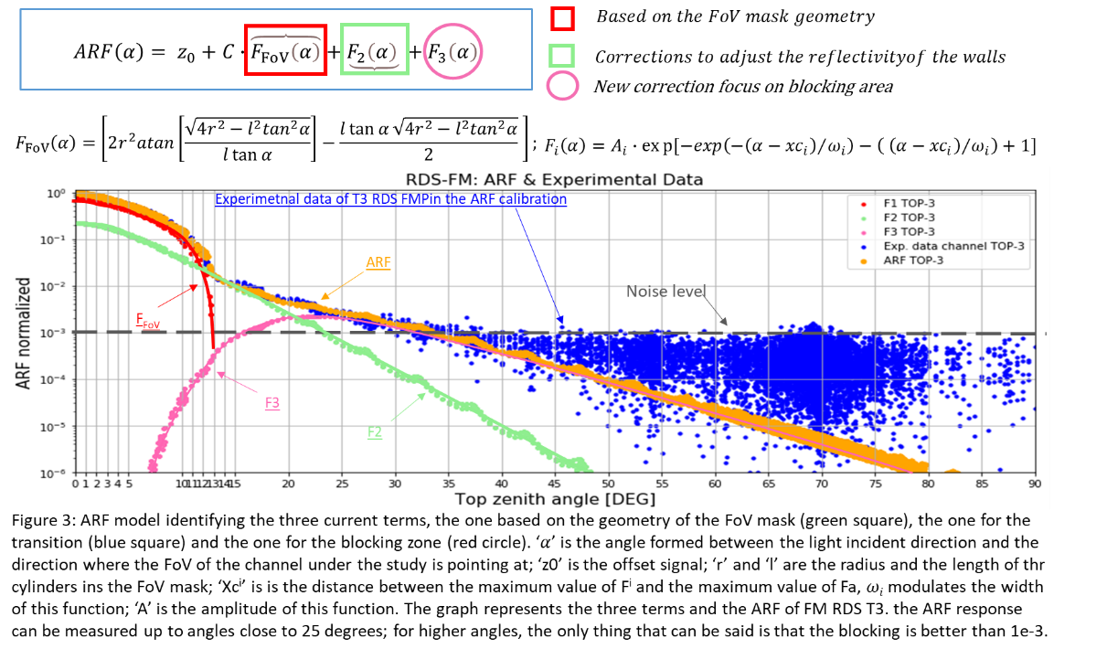
The angular sensor response (ARF) can be divided into 3 regions: the Field of View (FoV), the blocking and the transition regions. The blocking zone was found in early tests to be smaller than 1e-4(1e-2%) and was considered negligible.
The ARF model was implemented firstly with a function with two terms and it was valid only for the FoV and the transition regions. Blocking regions were found to be non negligible, so a new term was added to account for the sensitivity of the optical channels in those areas, though the experimental data are limited by the noise of the channels noise, in the order of 3e-4 (3e-2%).
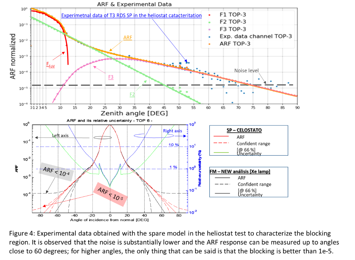
Despite this refinement, the retrieval models did not match the observations yet. For this reason, a characterization test of the blocking region was performed using the Flight Spare Model (FSM) in a heliostat. That test showed that the effect of the blocking region i is actually lower than 1e-5 counts, while the data from Mars was showing values in the order of 5e-4 (5e-2%).
Finally, a test was performed with the FSM unit to evaluate the effect of the deposited dust. The dust in the RDS structure increased the signal in the blocking zone of the optical channels in several orders of magnitude. Therefore, in order to determine the signal in this areas, it it is necessary to estimate the amount of dust deposited on the unit.
Conclusion
Improvements have been introduced in the process and analysis of the calibration of the multichannel radiometers manufactured by INTA for Mars missions. Peculiarities of the last developed instruments (RDS and SIS'22) and discrepancies between the results obtained in field campaigns and the actual measurements being obtained in Mars have been the reason for the upgrade of the calibration procedures and the analysis of their results.
How to cite: Jiménez Martín, J. J., García-Menéndez, E., Álvarez Ríos, F. J., Gonzalez-Guerrero Bartolomé, M., Apástigue Palacios, V., De Mingo Martin, J. R., Martinez Oter, J., Martín Beamonte, I., Montalvo Chacon, S., Rivas Abalo, J., Serrano Santos, F., Toledo Carrasco, D., and Arruego Rodríguez, I.: Calibration of RDS of Mars 2020 and SIS’22 of Exomars 2022 for Mars exploration, Europlanet Science Congress 2022, Granada, Spain, 18–23 Sep 2022, EPSC2022-1122, https://doi.org/10.5194/epsc2022-1122, 2022.