MITM7
Session assets
Orals: Thu, 22 Sep, 12:00–13:30 | Room Andalucia 1
With the gravimeter for small solar system objects (GRASS), absolute surface accelerations in the order of nano-g can be measured. It is an innovative and extremely compact sensor that will fly as part of ESA’s Hera mission onboard the Juventas CubeSat to the binary asteroid system Didymos. In 2027, Juventas will land on the secondary body of the system, Dimorphos, and GRASS will hence measure the local gravity vector and its temporal variations at the landing site. Apart from the direct mass determination, these measurements will help in synergy with other instruments to constrain the geological substructure as well as the surface geophysical environment.
The instrument is currently under development at the Royal Observatory of Belgium, funded by the Belgian PRODEX office and in cooperation with EMXYS in Spain.
The average gravitational force expected on Dimorphos’ surface is around 4.5 x 10⁻⁵ m s-2 (or 4.5 mGal, Figure 1). Apart from the self-gravitation of the body, centrifugal forces and the acceleration due to the main body of the system contribute to the surface acceleration. The temporal variation of the signal is driven by the dynamical state of Didymoon with respect to Didymain and the related librations.
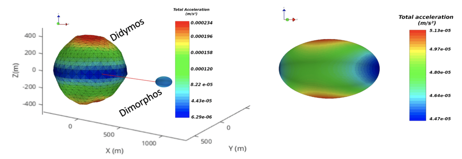 Figure1: Modeled surface gravity in the Didymos system (left) and on Dimorphos (right). Note that only a shape model for the primary body exists.
The table below lists the science objectives of the instrument for Dimorphos.
|
Objective |
Measurement |
|
S#1 Local subsurface inhomogeneities and global mass of Dimorphos. |
Determination of local gravity vector at landing location with accuracy of <1% in direction and amplitude. |
|
S#2 Dimorphos dynamical state |
Investigation of surface acceleration variations due to rotation kinematics, tides and orbital dynamics. Measurements as for S#1, but for several locations along the orbit of Dimorphos around Didymos. |
|
S#3 Global gravity solution, interior structure and surface mass transport |
Synergy of data with other instruments (radar, radio, CubeSat decent, star trackers) to obtain holistic view of gravity and interior. |
The gravimeter measurement system consists of monitoring the displacement and deflection of a flat spring due to a gravitational field by a capacitive transducer. Modulation of the measured g-vector by rotation allows the rejection of the zero-g bias. In addition, no levelling is required. The gravimeter will be calibrated in-situ by using electrostatic force to compensate acceleration forces.
Two orthogonally aligned gravimeter axes, each with a rotating sensor head, enable finally the reconstruction of the full 3D gravity vector. Figure 2 shows a CAD drawing with dimensions (left) and the vibration test model of the gravimeter (right).
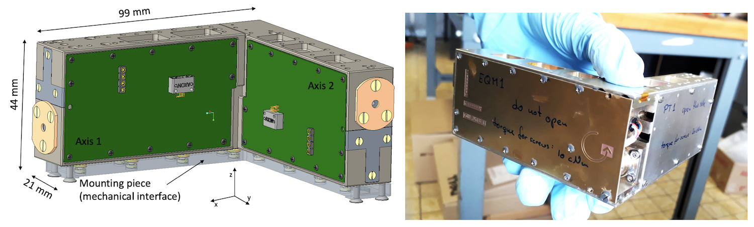
Figure 2: CAD drawing of the two-axes gravimeter (left) and a picture of the assembles GRASS vibration test model (right)
We will present the scientific background and application of the GRASS instrument on Dimorphos, the current instrument status, its implementation and first test results and give an outlook on future application of the instrument for other small planetary bodies.
How to cite: Ritter, B., Karatekin, Ö., Carrasco, J. A., Tasev, E., Alavés Mañogil, H., Noeker, M., Van Ransbeek, E., Noiset, G., and Berk Senel, C.: Measuring gravity with the GRASS instrument on the Hera mission, Europlanet Science Congress 2022, Granada, Spain, 18–23 Sep 2022, EPSC2022-1115, https://doi.org/10.5194/epsc2022-1115, 2022.
Introduction: The Solar System dust is the smallest Solar System building block, and therefore its study allows understanding the early stages of the Solar System formation. The comprehension of the Solar System formation and evolution processes is also constrained by the inventory and spatial distribution of volatiles in our System. In particular, the delivery process of volatiles of astrobiological interest (water and organics) to the Earth is a key issue to understand the life formation in our planet. Asteroids and comets may have been the source of these volatiles to the terrestrial planets’ atmospheres and to the Earth’s oceans. The boundary between asteroids and comets is not well defined, and many main-belt asteroids are probably volatile-rich and would become cometary if they were moved to the inner Solar System.
Piezoelectric Crystal Microbalances (PCMs) are widely used sensors to monitor dust and particles deposition processes in space and to characterize material outgassing in vacuum. This kind of sensors converts mass changes into fundamental resonance frequency variations, according to Sauerbrey equation [1].
In this work we present VISTA (Volatile in-Situ Thermogravimeter Analyser), one of the two scientific payloads on board MILANI Cubesat, as part of the ESA Hera Program. The MILANI Cubesat development is led by Tyvak International, prime contractor of a consortium composed by entities and institutions from Italy, Czech Republic and Finland. The main MILANI objective is executing a scientific mission aiming at studying the binary asteroid system Didymos-Dimorphos, characterizing the asteroid with a dust sensor, i.e. VISTA, and a spectrometer, i.e. ASPECT. VISTA is developed by an Italian Consortium composed by three Research Institutes: INAF-IAPS (National Institute of Astrophysics - Institute for Space Astrophysics and Planetology), CNR-IIA (National Council of Research – Institute of Atmospheric Pollution) and Politecnico di Milano.
HERA Mission goals: Hera is a planetary defence mission under development at the European Space Agency (ESA), launching in October 2024. Hera is the European contribution to the international Asteroid Impact Deflection Assessment (AIDA) cooperation, the first planetary defence mission, in collaboration with NASA, who is responsible for DART (Double Asteroid Redirection Test) kinetic impactor spacecraft. Hera will travel to a binary asteroid system, the Didymos-Dimorphos pair of near-Earth asteroids, and will study and characterize the asteroid system after the DART impact in September 2022. In the framework of Hera mission, VISTA will accomplish the following scientific goals: 1) detect the presence of dust particles smaller than 10 µm (residual dust particles from the impact and suspended dust in the binary system or coming from dust levitation process); 2) characterization of volatiles (e.g. water) and light organics (e.g. low carbon chain compounds) by using Thermo-Gravimetric Analysis (TGA) cycles (the desorption rates ad specific temperatures are used to characterize e volatiles and organics desorbed from the sensor surface); 3) molecular contamination monitoring in support to other Cubesat instruments and ASPECT spectrometer, coming from outgassing processes on-board the spacecraft, that usually happen in the first days or weeks in orbit.
VISTA Heritage: The Consortium has a considerable heritage in the design, manufacturing and testing of PCM-based instrumentation both for laboratory and space applications coming from different ITT-Emits ESA Projects: 1) CAM (Contamination Assessment Microbalance), developed for “Evaluation of an in-situ Molecular Contamination Sensor for space use” (2014-2016) (Figure 1); 2) CAMLAB (Contamination Assessment Microbalance for LABoratory) developed for “Development of a European Quart Crystal Microbalance” (2017-2019) (Figure 2).
Figure 1. PCM Engineering Model developed during CAM-ESA Project for space applications.

Figure 2. PCM breadboard developed during CAMLAB-ESA Project for laboratory applications.
Working principle: PCMs exploit the piezoelectric properties of quartz crystals, as mass deposition on the sensing area of the instrument induces variations of the crystal resonance frequency. The core of VISTA is composed of: 1) two quartz crystals mounted in a sandwich-like configuration (one sensing crystal and the other reference crystal); 2) a Thermal Control System (TCS), composed by two integrated heaters and a Thermoelectric Cooler (TEC); 3) a Proximity Electronics (PE). The instrument is also capable of performing Thermo-Gravimetric Analysis, a technique used to monitor thermal processes involving volatile compounds, e.g absorption/desorption and deposition/sublimation, by means of the built-in heaters. The TEC is used to cool down the sensor and enhance the condensation of particles on the microbalance. VISTA is capable of monitoring particles lower than 5-10 µm and sub-µm particles.
VISTA technical characteristics are shown in Table 1.

Table 1. VISTA technical characteristics.
The sublimated compounds can be characterized by calculating the enthalpy of sublimation ΔHsub, which can be retrieved with two methods: 1) by considering the deposition rates and using Van’t Hoff relation [3]; 2) by using Langmuir relation [4].
Conclusions and future works: In this work, the VISTA instrument working principle and heritage were presented. Qualification activities are currently ongoing on the VISTA Engineering Qualification Model (EQM), shown in Figure 3, in order to qualify the sensor within the expected mechanical and thermal environment and evaluate the instrument performances in a representative environment, prior integration on the MILANI Cubesat. The next phase of the research activities will be the manufacturing, integration and testing of VISTA Flight Model (FM), that will launch in 2024.

Figure 3. VISTA EQM developed for MILANI cubesat/HERA Space Mission.
References: [1] G. Sauerbrey 1959, Z. Phys., 155, 206-222; [2] Palomba E. (2016), OLEB, 46 (2-3); [3] S.W. Benson et al. 1968; [4] I. Langmuir, 1913.
How to cite: Palomba, E., Dirri, F., Longobardo, A., Gisellu, C., Biondi, D., Angrisani, M., Zampetti, E., Scaccabarozzi, D., and Saggin, B.: Volatile in-Situ Thermogravimeter Analyser (VISTA) payload developed for MILANI cubesat for HERA Space Mission, Europlanet Science Congress 2022, Granada, Spain, 18–23 Sep 2022, EPSC2022-927, https://doi.org/10.5194/epsc2022-927, 2022.
Introduction: Quartz Crystals Microbalances (QCMs) are widely used sensors for monitoring and characterizing dust and particles deposition processes in different planetary environments and measuring material contamination coming from outgassing sources in space, in support to other instruments (e.g. spectrometers). Furthermore, they are capable of detecting and measuring the presence of volatile com-pounds of astrobiological interest such as water and organics. These measurements can be particularly relevant when performed on primitive asteroids or comets, or on targets of potential astrobiological interests, e.g. Mars [1]. These sensors convert mass changes into fundamental resonance frequency variations, according to Sauerbrey equation [2].
The VISTA (Volatile In Situ Thermogravimetry Analyser) instrument is a QCM-based device able to perform measurements of abundance of volatiles and dust particles in planetary and asteroidal environments. The instrument can characterize the planetary regolith from 5-10 µm to sub-µm particles and monitor the contamination processes on board satellites (cubesat, etc.) caused by molecular outgassing. VISTA is one of the two scientific payloads of MILANI CubeSat, developed by Tyvak International that leads a consortium composed by entities and institutions from Italy, Czech Republic and Finland, in the framework of the Hera program of the European Space Agency (ESA). Hera, due to launch in 2024, is the ESA part of the Asteroid Impact & Deflection Assessment (AIDA) international collaboration with NASA, who is responsible for the Double Asteroid Redirection Test (DART) kinetic impactor spacecraft. The main objective of MILANI is the study of the binary asteroid system Didymos-Dimorphos, characterizing the asteroid with a dust sensor (VISTA) and a spectrometer (ASPECT).
In this work, the calibration operations and the performance tests, to assess VISTA capability of characterizing volatile compounds and simulant contaminations in vacuum chamber at low temperatures. The sensor has been developed by an Italian Consortium composed by three Research Institutes: INAF-IAPS (National Institute of Astrophysics - Institute for Space Astro-physics and Planetology), CNR-IIA (National Council of Research – Institute of Atmospheric Pollution) and Politecnico di Milano and led by INAF-IAPS.
Figure 1. VISTA EQM developed for ESA Hera space mission.
Working Principle: The instrument core is a QCM whose frequency variations directly depends on the deposited sample mass on the crystal surface during sublimation, condensation and absorption/desorption processes. The instrument consists of: 1) two quartz crystals mounted in a sandwich-like configuration; 2) a Thermal Control System (TCS), composed by two integrated heaters and a Thermoelectric Cooler (TEC); 3) a Proximity Electronics (PE). VISTA is also capable of performing Thermo-Gravimetric Analysis, which is a technique used to monitor thermal processes involving volatile compounds, e.g. deposition/sublimation and absorption/desorption. It can also monitor particles lower than 5-10 µm and sub-µm particles [1].
Calibration: The QCM frequency can change not only due to the mass deposition/release, but also due to the variation of environmental parameters, such as temperature and pressure. In order to disentangle frequency variations due to mass deposition and environmental parameters, the sensor is calibrated by measuring the frequency as a function of temperature. According to literature [3], the frequency-temperature curve follows a third-degree polynomial (Figure 2).
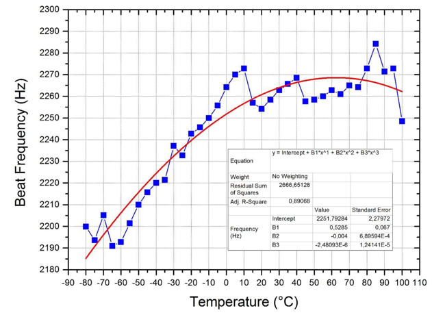
Figure 2. QCM frequency as a function of temperature in vacuum.
Performance tests: VISTA capability to detect contaminant depositions and to monitor the accumulation and desorption processes is verified by placing an effusion cell containing an organic compound, used as a contamination source, placed in the Field Of View (FOV) of the sensing crystal and heated up to 100°C. The experimental setup is shown in Figure 3.
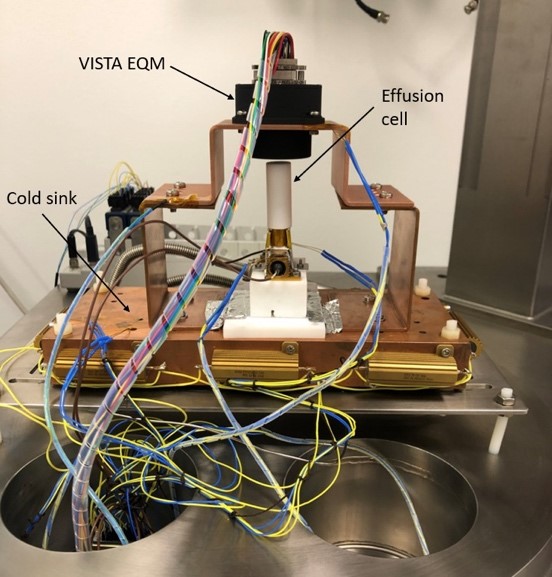
Figure 3. VISTA EQM experimental setup for contamination simulation.
The QCM is connected with four screws with a copper U shape and in contact with a cold sink set to -10°C to help the molecules condensation on the crystal surface. The frequency is monitored during the tests and the deposited flux can be retrieved (Figure 4) at each temperature set point.
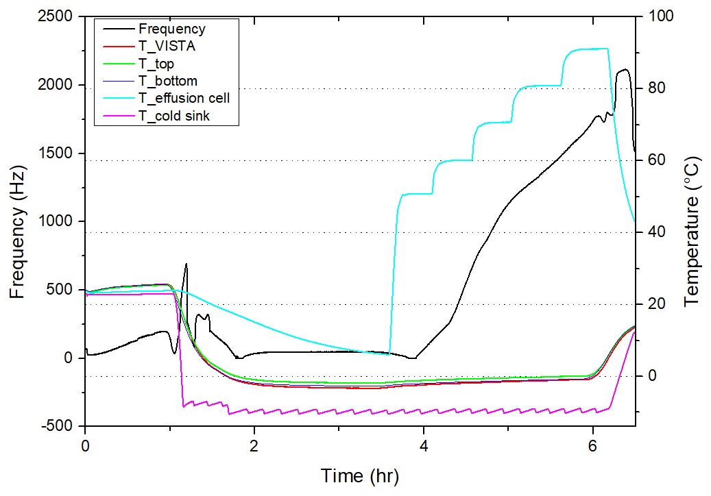
Figure 4. Deposition test from +50°C to +100°C.
Two methods can be used to retrieve the enthalpy of sublimation ΔHsub by using the deposition rates, i.e. the Van’t Hoff relation [4] or Langmuir relation [5]. Thus, by measuring two different deposition rates, k1 and k2, at two different close temperatures T1 and T2, it is possible to obtain the compound ΔHsub by means of Van’t Hoff relation or throughout the temperature range by using Langmuir relation.
TGA cycles are then performed by heating the crystals by means of the built-in heaters. After the heating cycles, the frequency returns to its initial value, thus indicating that all the deposited mass desorbed during the test (Figure 5).
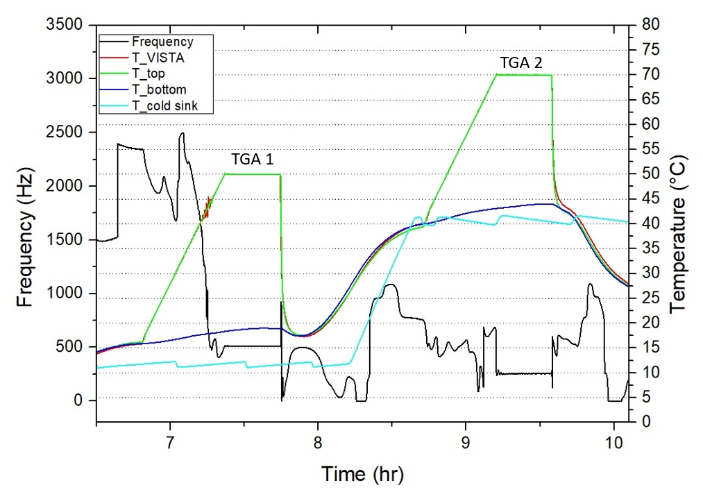
Figure 5. TGA cycles from +15°C to +50°C and from +40°C to +70°C.
The desorption rates from crystals surface can be used as well to calculate the ΔHsub and compare it with the ΔHsub results obtained during the depositions/contamination processes.
References: [1] E. Palomba et al (2016), OLEB, 46(2-3; [2] G. Sauerbrey (1959), Z. Phys., 155, 206-222; [3] D. Salt (1987); [4] S.W. Benson et al., 1968; [5] I. Langmuir, 1913.
How to cite: Gisellu, C., Dirri, F., Palomba, E., Longobardo, A., Biondi, D., Angrisani, M., Zampetti, E., Scaccabarozzi, D., and Saggin, B.: Calibration and performance tests of VISTA, a microbalance for asteroid dust characterization and contamination for space mission applications, Europlanet Science Congress 2022, Granada, Spain, 18–23 Sep 2022, EPSC2022-790, https://doi.org/10.5194/epsc2022-790, 2022.
Thermal Infrared Imager TIRI onboard Hera is now being developed for the investigation of the binary asteroid Didymos and Dimorphos in the European Space Agency Hera mission. This instrument uses a heritage from the Thermal Infrared Imager TIR on Hayabusa2, which observed the C-type asteroid 162173 Ryugu. In the Hera mission, its updated version of instrument is based on Lynred PICO 1024 Gen2 bolometer array (1024 x 768 effective pixels) with almost 4 times higher spatial resolution than TIR. The wavelength range shows 8-14 µm for the thermal average images, as well as 7.8, 8.6, 9.6, 10.6, 13.0 deg for multi-bands). Its FOV covers 13.3 x 10.0 deg with the spatial resolution of 0.013 deg/pixel.
TIRI is now in the test process to check its full functions and performances as well. The calibration for TIRI is to check its focus, to conduct radiometric and geometrical corrections, identification of materials (like terrestrial rocks and meteorites). A set of apparatus were prepared by the TIRI PI team using the collimator (Aperture: 200mm dia., temperature range of -20 to 150℃, Focal position is 60 deg or higher), the flat cavity blackbody ( 175 x 175 mm, -20 to 125 ℃ for fact change of temperature), and a cold plate plus the cryocooler for the target sample (room temperature to -123 deg). There are some rocks and meteorites to be set as the multiband test samples at the target material, With these information and the presentation, details of the TIRI preparation and development are shown. The test results for TIRI will be presented with some data set and physical properties using the sample.
How to cite: Okada, T., Tanaka, S., Sakatani, N., Shimaki, Y., Arai, T., Senshu, H., Demura, H., Sekiguchi, T., Kouyama, T., Kanamaru, M., and Ishizaki, T.: Calibration of the Thermal Infrared Imager TIRI onboard Hera, Europlanet Science Congress 2022, Granada, Spain, 18–23 Sep 2022, EPSC2022-1191, https://doi.org/10.5194/epsc2022-1191, 2022.
Introduction: The dust ejected by cometary nuclei encodes valuable information on the formation and evolution of the early Solar System. Several short-period comets have already been studied in situ[1], but their pristine condition was modified by multiple perihelion passages. Dynamically new comets (DNCs) remain pristine bodies since they never visited the inner Solar System, stationing more than 2000A.U. far away from the Sun in the Oort cloud.
Comet Interceptor (CI) is the first F-class space mission selected by the European Space Agency to study a DNC or an interstellar object entering the inner Solar System for the first time[2]. The Dust Impact Sensor and Counter (DISC) is an instrument included in the Dust Field and Plasma (DFP) suite, part of the CI payload, dedicated to characterizing the dust encountered by the spacecraft (S/C) during its flyby in the coma of the target DNC. DISC will measure hypervelocity impacts (HVIs), in the range 10–70km/s, with cometary dust particles of 1–400μm diameter. It aims to characterize the mass distribution of dust particles in the range 10-15–10-8kg, and retrieve information on dust structural properties from impacts duration[3].
DISC design: DISC is a 121×115.5×46mm3 aluminum box containing both the detection system and the electronics (Fig.1). The former consists in a 100×100×0.5mm3 aluminum plate with three piezoelectric traducers (PZTs) at its corners. HVIs induce shockwaves in the sensing plate. Far from the impacted area, such waves become acoustic Lamb waves that propagate up to the PZTs, which start to vibrate at their resonant frequency. A couple of electronic boards at the bottom of the unit allows to retrieve the particles momentum and kinetic energy from PZTs vibration signal.
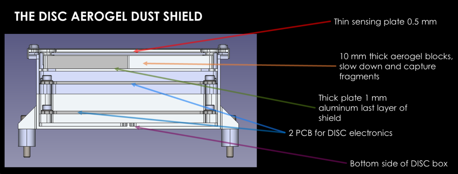 Fig.1: DISC sensing element and dust shield design.
DISC detection system is derived from the GIADA Impact Sensor measurement subsystem, that was designed to measure impacts of slow particles[4]. During CI flyby, some hypervelocity dust particles might perforate DISC outer sensing diaphragm and represent a serious hazard for the instrumentation. A dedicated mechanical element preliminarily designed as made of four 1cm-thick aerogel blocks and a 1mm-thick aluminum frame was integrated into DISC design to shield the entire S/C from such dangerous impacts.
Two key aspects need to be verified to ensure that the instrument is suitable for CI aims:
- DISC capability to survive the expected coma dust environment;
- DISC capability to measure the momentum/energy of impacting particles in the aforementioned size and mass ranges.
Dust shield assessment: We verified DISC dust shield performance using a two-stage Light-Gas Gun (LGG) (Open University, Milton Keynes) to shoot mm-sized particles of various materials at speeds around 5km/s[5,6]. This facility allowed to test the instrument resistance to momenta in the range 10-2–10-1kg·m/s and to energies of the order of 102J. The dust shield showed good resistance up to energies of about 200J, released by a 3mm nylon bead at 5.5km/s. DISC resistance to higher-energy particles can be improved by increasing the aerogel thickness, without any further modifications to the general design.
These experiments proved that DISC is compatible with the foreseen coma dust environment. Integrating a thicker aerogel layer in the design will reduce the risk of failure due to higher-energy particles to low enough values even for the S/C more exposed to the dust flux. The S/C beneath DISC unit is further protected by DISC lower layers.
DISC performance: DISC will measure momenta in the range 10-11–10-3kg·m/s[7]. The LGG facility allows to reach high momentum values by shooting heavy particles, but their collision dynamics is very different from what expected for cometary dust. A different strategy to simulate the foreseen impact momentum range is needed.
A Van der Graaf (VdG) gun can shoot μm-sized dust particles up to 20km/s, reproducing momenta of 10-9–10-7kg·m/s[8].
The tested impact parameters range can be extended by simulating HVIs effects with a high-power pulsed laser beam. Laser intensity, beam dimension, and pulse duration can be regulated to respectively match impact pressure, section, and shock duration of the corresponding particle[9]. Laser intensities of 109–1010W/cm2 can generate surface pressures from kbar to Mbar, typical of cometary dust particles colliding at 3–6km/s. Using our Nd:YAG laser (λ=1064nm), which emits τ=6ns pulses with pulse energy of Epulse=1.2J, we can cover a momentum range of 10-10–10-5kg·m/s. Since laser simulated and VdG real impacts share part of the released momentum range, laser shots can be calibrated and their representativity verified with real collisions.
The energy range expected for dust impacts measured during CI flyby is 10-7–102J. Laser simulated impacts cannot reach the higher energy values. However, the energy/pulse duration range is pretty vast and with some attenuators and pulse reducers the central/left part of the parameters space (around mJ energy and ns pulse time) could be reasonably covered.
Fig.2. shows the optical setup: a polarizer attenuator splits the beam and allows to regulate its power; a couple of mirrors prevents backwards reflections to get to the laser output aperture; a beam expander enlarges the beam, which enters a vacuum chamber and is focused by a plano-convex lens on the DISC breadboard mounted on a 3-axis translational stage. The vacuum chamber is fundamental to prevent plasma generation in air around the focus.
 Fig.2: Optical setup for high-power pulsed laser simulated HVIs.
By properly tuning the laser parameters, this strategy allows to achieve representative simulations of cometary dust HVIs. In addition to assess DISC performances, simulating the same impact many times provides large statistics to calibrate DISC detection system and momentum/kinetic energy retrieval methodology with great accuracy.
References: [1] Keller H. U. and Kührt E. (2020) Space Sci. Rev., 216(1), 1–26. [2] Snodgrass C. and Jones G. H. (2019) Nat. Commun., 10(1), 1–4. [3] Della Corte V. et al. (2021) LPSC LII, Abstract #2332. [4] Esposito F. et al. (2002) Adv. Space Res., 29(8), 1159–1163. [5] McDonnell J. A. M. (2006) Int. J. Impact Eng., 33(1–12), 410–418. [6] Hibbert R. et al. (2017) Procedia Eng., 204, 208–214. [7] Di Paolo F. et al. (2021) LPSC LII, Abstract #1238. [8] Friichtenicht J. F. (1962) Rev. Sci. Instrum., 33(2), 209–212. [9] Pirri A. N. (1977) Phys. Fluids, 20(2), 221–228.
How to cite: Ferretti, S., Della Corte, V., Piccirillo, A. M., Rothkaehl, H., Sylvest, M., Patel, M., Ertel, H., Millinger, M., Bertini, I., Fiscale, S., Longobardo, A., Inno, L., Rotundi, A., Ammannito, E., and Sindoni, G.: Analysis of dust shield and detection system response to hypervelocity impacts for Comet Interceptor Dust Impact Sensor and Counter, Europlanet Science Congress 2022, Granada, Spain, 18–23 Sep 2022, EPSC2022-1163, https://doi.org/10.5194/epsc2022-1163, 2022.

Introduction:
MiniPINS is an ESA study to develop and prototype miniaturised surface sensor packages (SSPs) for Mars and the Moon. The study aims at miniaturising the scientific sensors and subsystems, as well as identifying and utilizing commonalities between Mars and Moon SSPs, allowing to optimise the design, cut costs and reduce the development time.
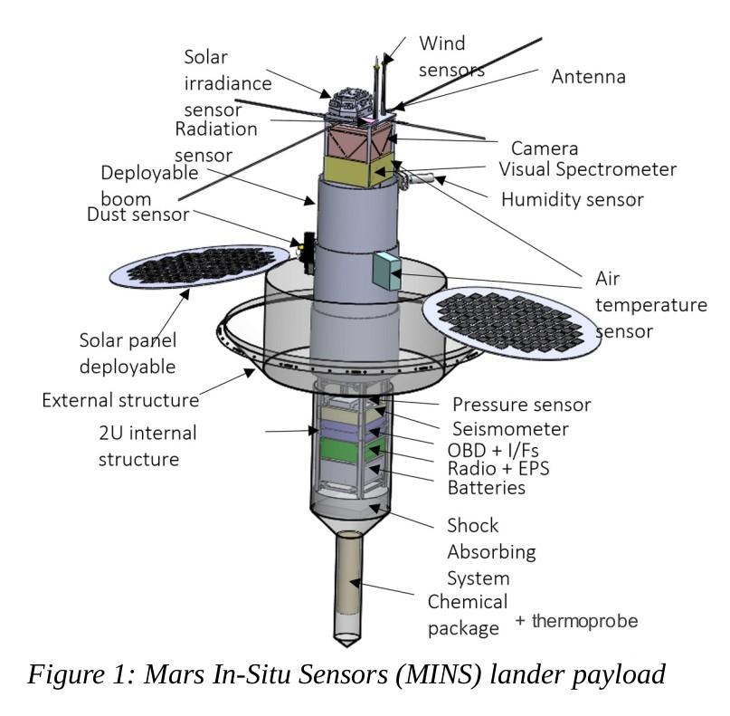
Mars In-Situ Sensors (MINS) is a penetrator with approx. 25 kg mass, piggy-backed by another Mars mission spacecraft to Mars. In total 4 identical penetrators are deployed to different landing sites either from the approach orbit or Mars orbit. The design of MINS has significant heritage from FMI’s MetNet mission design[1]. The entry, descent and landing sequence of MINS is completely autonomous and controlled by its on-board computer. In the Martian atmosphere the penetrators undergo aerodynamic braking with inflatable breaking units until they reach the target velocity of 60-80 m/s for entering the Martian surface. The nominal mission duration is one Martian year.
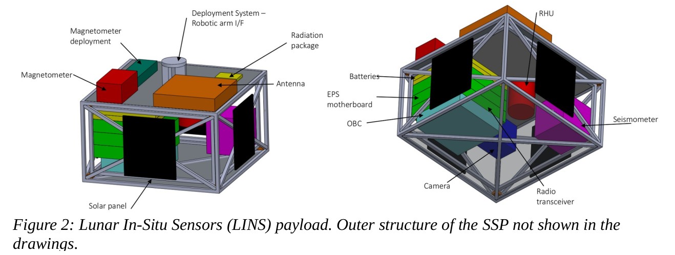
Lunar In-Situ Sensors (LINS) is a miniature 7 kg station deployed on the Moon surface by a rover. LINS mission consist of 4 surface stations deployed to different sites within the rover’s traveling perimeter. The LINS scientific package consists of several scientific instruments to study the Moon for 2 years.
Mars SSP sensors:
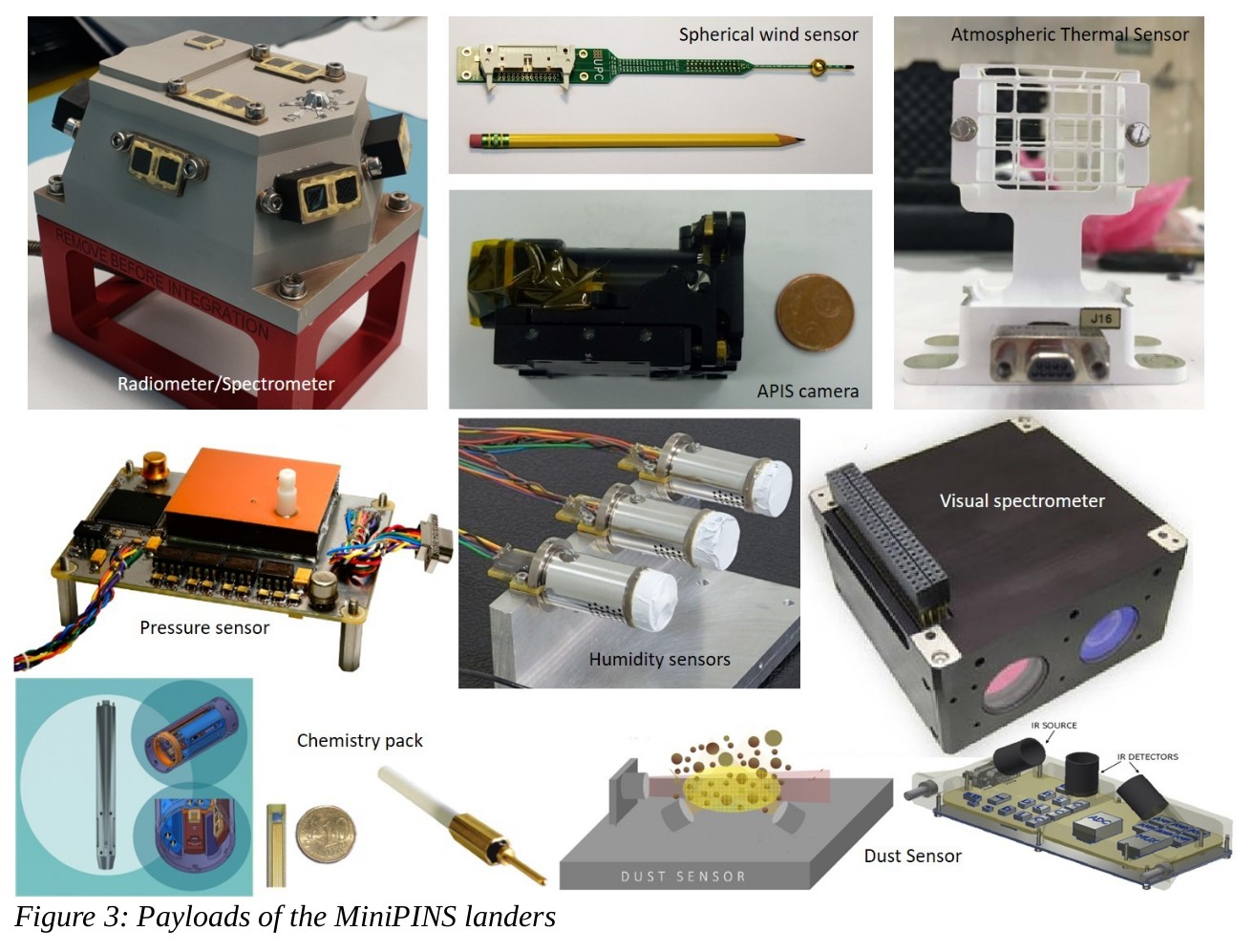
MINS will study the Martian atmosphere, seismology and chemistry. The MINS payload consists of a camera, a visual spectrometer, a meteorological package, an impact accelerometer, soil thermoprobes, a chemistry probe, a seismometer and a radiation monitor. Many of the instruments have Mars heritage but additional qualification is required due to landing shock.
The meteorological package consists of air temperature sensors, pressure sensor, relative humidity sensor, wins sensors, dust sensor and solar irradiance sensor. Pressure and humidity sensors are provided by FMI and the sensors have heritage from multiple Mars missions like the M2020 Perseverance rover[2]. Air temperature sensors are provided by CAB and they have heritage from MSL[3], InSight[4] and M2020[2]. Solar irradiance sensor (SIS)[5] is provided by INTA and the technology has been used in several Mars missions[6]. The selected design for MiniPINS is the SIS for ExoMars ‘22. Also based on ExoMars ‘22 METEO is the dust sensor by UC3M.
The chemistry probe is a new design developed by CAB. It is composed of several miniature sensing needles that share an acquisition electronics to measure pH, salinity, water content, conductivity and temperature of the Martian regolith. The current TRL is 6. The thermoprobe is also a new design developed by UPC for characterizing the thermophysical properties of the regolith.
The visual spectrometer selected for MiniPINS is based on tunable Fabry-Pérot interferometer (FPI) technology by VTT Technical Research Centre of Finland[7]. The piezo-actuated FPI technology has previously flown on board nanosatellites Aalto-1, Reaktor Hello World and PICASSO demonstrating operation in different wave lengths. Due to its maturity and flight-proven performance, the near-IR concept is the baseline for the MINS spectrometer.
Moon SSP sensors:
LINS proposal is focused on two principal science objectives: understanding the structure and composition of the lunar interior and the characterization of the lunar surface environment in view of human exploration and resource extraction. The placement of a network of short period seismic stations will allow determining the thickness of the lunar crust (upper and lower) and its lateral variability. Due to smaller size the LINS has fever scientific sensors and many are common with the MINS packages. Magnetometer selected for LINS is based on the triaxial magnetometer developed by INTA for MetNet Mars mission. The sensor will require some modifications and adaptation of the ejection mechanism as well as temperature qualification for Lunar conditions.
Shared sensors:
The cameras of both MINS and LINS are based on the Athermalized Panchromatic Imaging System (APIS) low-resolution refractive camera used by INTA as a CubeSat payload which flew on-board the OPTOS satellite. It is based on a 1.3 MP CMOS image sensor from Cypress Semiconductor Corporation but the optics will be redesigned taking into account the applicable requirements for each mission.
Miniature wind sensors (Mars) and thermoprobes are based on the same sensor structure developed by UPC. The new type of sensor is a spherical shell divided into four sectors. To sense temperature and provide heating power, a customized 3 x 3 mm silicon die, including a platinum resistor, is attached to the inner side of each sector. In MINS the wind sensors are located in the deployable mast and the soil sensor is in a compartment below the surface in contact with the regolith. For LINS a dedicated deployment mechanism must be developed for the soil probe. The wind sensors and soil probes are currently in TRL 6.
The short period seismometer is based on a miniature MEMS resonator by Imperial College, previously used in InSight[8]. For LINS a variant of the sensor, called the Silicon Seismic Package, (SSP)[9] is proposed.
The impact accelerometer of MINS will be a new development. To miniaturise the accelerometer, a commercial part from PCB Piezotronics has been selected as the basis of the sensor and the complete sensor assembly will be developed and qualified by INTA. Lunar SSP also includes an accelerometer which is used to determine the attitude of LINS. It is based on an Analog Devices component ADXL327BCPZ, already qualified by INTA for Mars, but LINS missions requires even larger temperature range so additional qualification is foreseen.
The radiation monitors included in both missions are based in the Metal-Oxide-Semiconductor Field-Effect-Transistor (MOSFET) dosimeters. Proposed provider of MOSFET dosimeters is Tyndall National Institute.
Project status:
The MiniPINS study, consisting of project phases A and B1, is nearly completed and a final review was held in autumn 2021. As a follow-up, the European Space Agency is facilitating an industrial development of European inflatable deceleration system.
How to cite: Hieta, M., Genzer, M., Haukka, H., Kestilä, A., Arruego Rodríguez, I., Apéstigue Palacio, V., Reina Aranda, M., Gonzalo Melchor, A., Martínez Oter, J., González-Guerrero Bartolomé, M., Ortega, C., Camañes, C., Dominguez-Pumar, M., Espejo Meana, S., Guerrero, H., and Rodríguez-Manfredi, J. A.: State-of-the-art miniaturised science instruments of the MiniPINS landers, Europlanet Science Congress 2022, Granada, Spain, 18–23 Sep 2022, EPSC2022-820, https://doi.org/10.5194/epsc2022-820, 2022.
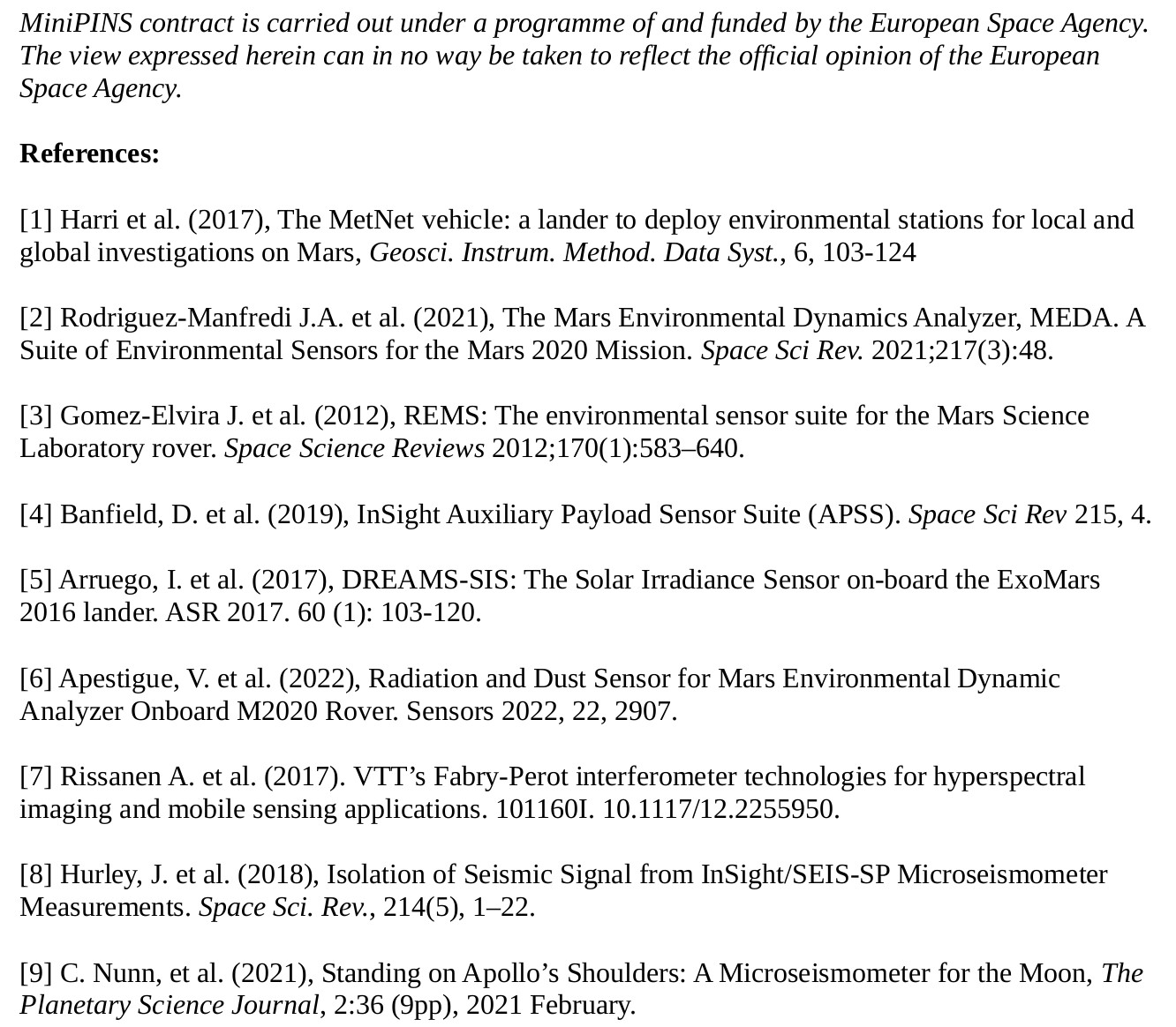
The Visual Monitoring Camera (VMC) is a small camera onboard Mars Express, initially intended to provide visual confirmation of the separation of the Beagle 2 lander. In 2007, a few years after the end of its original mission, VMC was turned on again to obtain full-disk images of Mars for outreach purposes (Ormston et al., 2011). As VMC obtained more images, the scientific capabilities of the camera became evident (Sánchez-Lavega et al., 2018), and finally the small camera was upgraded to be a new scientific instrument, with an agreement between the European Space Agency (ESA) and the University of the Basque Country (Spain; UPV/EHU). In this work we describe the calibration and technical efforts that are allowing us to maximize the scientific output from this small camera.
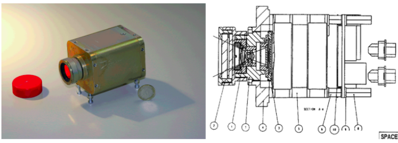
Figure 1. Image of VMC before launch (left) and scheme from the Flight User Manual (right)
VMC is also called the Mars webcam, as it is similar to a typical webcam of the 2000s. The sensor has a a 640x480 pixel array, and a Field of View (FOV) of 30ºx40º. This wide FOV, together with the elliptical orbit of Mars Express, enables full-disk observations from apocenters, which are the most common product of VMC. It is also possible to use this wide FOV to image large sections of the limb, and therefore monitor the occurrence of high altitude aerosols, as shown by Sánchez-Lavega et al. (2018).
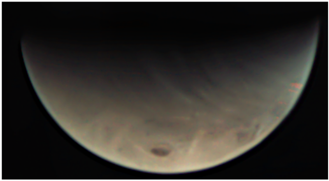
Figure 2. Full disk of Mars as seen by VMC.
Operations
Since 2018 VMC operations follow a similar routine as those used for other science instruments. The Science Ground Segment takes care of the Medium Term Planning (MTP) following the inputs from the science team. The science team performs the Short Term Planning (STP). Fig. 3 shows a typical VMC observation, which consists of a default image, followed by one to several loops of 6 images that use a set of predefined exposures. The exposure times are set to maximize the dynamic range of the final science products obtained by combining the individual images.
Figure 3. Scheme of a typical VMC observation.
Calibration of images
The images are calibrated following the standard scheme of subtracting a dark current and dividing by a flatfield image. The flat field correction is much more relevant than the dark correction in the quality of the final images after calibration. No onground calibration is known for VMC, therefore the dark current and flat-field corrections used are based only on in-flight observations. The dark was obtained by pointing VMC to the sky, specifically the area of Eridanus, where few bright stars are present.
The flat-field was created using dark-corrected images of flat portions of Mars that were well and uniformly illuminated, as free as possible from large structures, and as flat as possible.
Calibrated images are routinely archived at ESA’s Planetary Science Archive (PSA), as described by Ravanis et al. (2020)
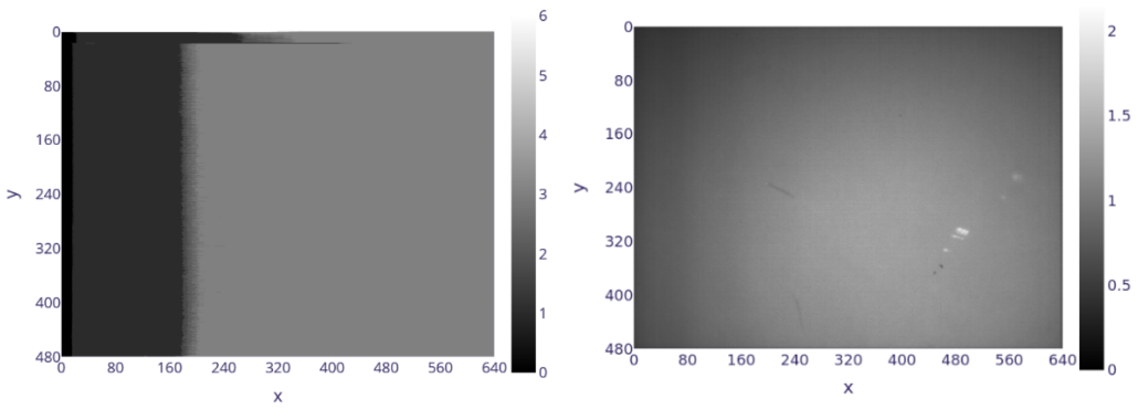
Figure 4. VMC dark (left) and flat (right).
Geometry
The original documents indicate the design parameters for the orientation of VMC in the reference frame of MEX, and for the pixel resolution (iFOV). However, the accurate parameters once VMC was mounted on MEX were never measured on the ground. In addition to this, we find that the timestamp of images suffers a random shift of a few seconds. As a result, we have 5 free parameters: 3 Euler angles for the attitude relative to the MEX reference frame; the pixel resolution (iFOV); and the shift in time from the actual timestamp to the labeled timestamp.
In order to determine the attitude and iFOV of VMC relative to Mars Express, we used images showing stars. Many of these observations covered the stars of the constellation of Orion, because several suitable stars are present in that region of the sky. During these observations the spacecraft maintains a fixed attitude, therefore, the time related uncertainty is not present and only 4 free parameters remain: 3 Euler angles, and the pixel size. These parameters are shown in table 1.

Table 1. VMC geometric parameters as given by the Flight User Manual (FUM) and calibrated values.
The shift in time was estimated from observations showing Phobos. The relative speed of Phobos as seen from Mars Express is high, and therefore it is possible to use its position as an accurate clock. We find that our images are usually obtained between 6 and 13 seconds before the labeled time, but we find random variations. Subtracting 10 seconds is considered a good strategy in most cases, but this uncertainty remains as a limitation.
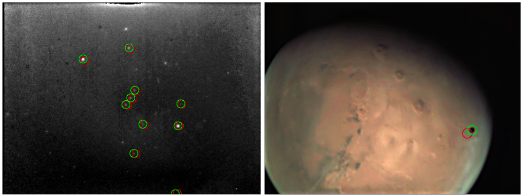
Figure 5. VMC image showing the stars of Orion (left), and Phobos in front of Mars (right). Red circles represent the expected position before calibration. Green circles are the expected positions according to the new calibration.
Conclusions
Within the expectable limitations, the performance of this new instrument is very good and VMC is enabling novel science results and techniques (e.g. Hernández-Bernal et al. 2021). This is in part because VMC provides some capabilities that are not common among instruments in orbital planetary missions. Even with no on-ground calibration available, it has been possible to calibrate the camera, both photometrically and geometrically. Some hardware limitations remain, and others have been partially overcome with specially developed operational strategies.
References
Hernández‐Bernal et al. (2021). A Long‐Term Study of Mars Mesospheric Clouds Seen at Twilight Based on Mars Express VMC Images.
Ormston et al. (2011) An ordinary camera in an extraordinary location: Outreach with the Mars Webcam.
Ravanis et al. (2020). From engineering to science: Mars Express Visual Monitoring Camera's first science data release.
Sánchez-Lavega et al. (2018). Limb clouds and dust on Mars from images obtained by the Visual Monitoring Camera (VMC) onboard Mars Express.
How to cite: Hernández Bernal, J., Cardesín Moinelo, A., Hueso Alonso, R., Ravanis, E., Burgos Sierra, A., Wood, S., Marín Yaseli de la Parra, J., Merrit, D., costa Sitja, M., Escalante, A., Grotheer, E., Esquej, P., Dias Almeida, M., Martin, P., Titov, D., Wilson, C., del Río Gaztelurrutia, T., Sánchez Lavega, A., and Sierra, M.: The Visual Monitoring Camera on Mars Express: calibrating a new science instrument made from an old webcam orbiting Mars, Europlanet Science Congress 2022, Granada, Spain, 18–23 Sep 2022, EPSC2022-684, https://doi.org/10.5194/epsc2022-684, 2022.
The composition of the Martian atmosphere and its dust content is a key factor for understanding the climate of the Red Planet, which is of vital importance to enable future human exploration. The use of atmospheric LIDARs to characterize densities and sizes of aerosol with a height profile, is commonly used on Earth. However, Earth LIDARs are heavy and very power-demanding, which make them not easily on-boardable for planetary exploration.
We propose the development of a compact LIDAR aimed at providing the most precise characterization of the suspended dust and clouds of the atmosphere of Mars to-date, while maintaining very reduced power, mass and volume envelops to facilitate its accommodation in a wide variety of landed assets.
Rationale and heritage
In the past years, INTA has developed four miniature radiometers for different missions: MetSIS for MetNet Lander [1], DREAMS-SIS for Schiaparelli [2], SIS’20 for Kazachok [3] and RDS for Perseverance [4]. All of them, at different levels depending on their complexity, allow the estimation of the atmospheric optical depth with high time resolution, detection of clouds and estimation of the dust concentration vertical profile. A natural step forward to complement our capabilities, especially for the dust profile and characterization of clouds, is a LIDAR.
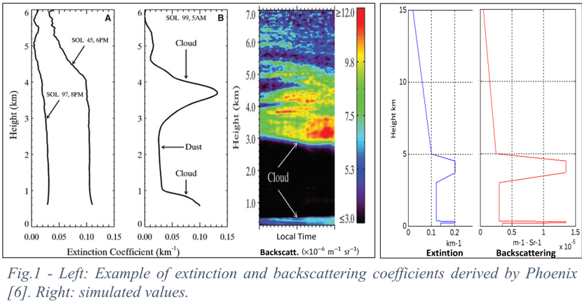
There is only one LIDAR that has already operated on Mars, on board the Phoenix mission. With a 2-wavelengths configuration at 532 and 1064 nm but without depolarization, it operated in the North Pole of Mars for 90 sols [5]. The laser pulses had a power of 30-40 kW and duration of 10 ns. Total mass was 6 kg and the power consumption 30W.
A '2B+1d' LIDAR configuration is proposed here to obtain the Particle Backscatter Coefficient (PBC) at two wavelengths (2B), and the depolarization ratio at one of them (1d). They both are used to obtain three LIDAR parameters relevant for dust and cloud characterization: the particle linear depolarization ratio (PLDR), the lidar ratio (LR), and the colour ratio (CR). The intended range is set around 20 km, depending on the scenario, and depolarization measurement capability shall be incorporated.
Key technologies for miniaturization
The target mass and power envelop are <4 kg and <15W, respectively. The instrument should be capable of operating at atmospheric temperatures below -100°C to minimize the requirements for its accommodation. Achieving those goals will be a technological challenge, and it will be necessary to use technologies not employed before in this scenario. Several key aspects are identified:
- Pulsed semiconductor laser diodes are proposed for the transmitter, instead of usual (and bulkier) diode-pumped, Q-switched solid-state lasers. This reduces the emitted energy and in turn requires higher repetition rates to improve the Signal-to-Noise ratio.
- Silicon Photomultipliers, also known as Multi Pixel Photon Counters, will be used as detectors. They allow lower biasing voltages than other high-gain technologies, while they show some trade-offs such as their so-called "cross talk" noise. Its performance under the applicable thermal and radiation environments must be addressed.
- The use of new synthesis methods to obtain very low thermal expansion coefficient (CTE) materials (crystalline β- eucryptite) to reduce the thermal requirements related to structure and alignment.
- To reduce the size of the optics and to mitigate the complexity of the collimation of a semiconductor laser (with large spots and emission apertures), 'free form' optics will be considered in the optical design.
- From the signal processing point of view, the aim is to design a receiver that autonomously adapts the measurement mode (analogue or pulse counting) and parameters (e.g., variable time intervals for pulse-counting) in real time, providing the best signal quality vs. vertical resolution compromise for each altitude.
Feasibility
To preliminarily assess the feasibility of this LIDAR to reach a scientifically meaningful range, we have performed several simulations of the expected signal and signal-to-noise ratio using extinction and backscattering profiles representative of different dust conditions on Mars, together with technical data extracted from the datasheets of real pre-selected parts and opto-mechanical parameters values that we consider feasible for a compact instrument as the intended one. Emitted pulses have a power of 600W and a duration of 150ns. We have simulated three different background illumination scenarios: night, twilight, and midmorning, as this is critical from the point of view of the “offset” signal it generates (that must be filtered out) and the noise associated with it. We employed worst-case (high) diffuse radiance values on Mars. Extinction and backscattering coefficients have been extracted from Phoenix LIDAR measurements [6], and background illumination values from RDS measurements in Perseverance.
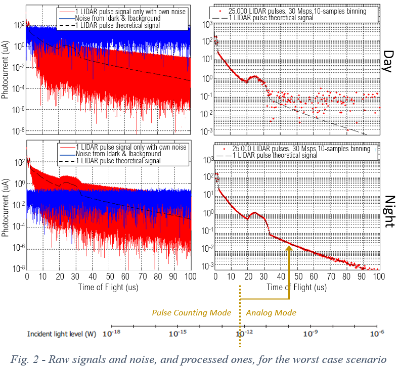
The conclusion is that, with adequate signal processing, we should be capable of reaching 4 km during the day, 6-7 at twilight and 15 at night, for the worst-case scenario. 20 km are feasible in better scenarios.
On-going activity and next steps
A breadboard prototype of the system is being built at INTA for only one channel (one wavelength; no polarization) based on pre-selected pulsed laser diode and silicon photomultiplier, with standard off-the-shelf optical parts and filters. Preliminary laboratory and outdoor measurements will be done to validate the simulations and confirm the feasibility of reaching a meaningful range with the strict miniaturization constraints.
Low-temperature characterization of the emitters and detectors, as well as Displacement Damage tests to assess their robustness to the radiation environment will be done by the end of the year. The electronic design has a large heritage from previous Martian sensors as the ones mentioned above, all of them designed to operate down to -130ºC with no heating. Next steps will include thermal cycling testing of the optics and the support materials and feasibility analysis of the optomechanical frame to face such conditions.
[1] Ari-Matti Harri et al., Geosci. Instrum. Method. Data Syst., 6, 103–124, 2017.
[2] I. Arruego et al., Advances in Space Research 60 (2017) 103–120.
[3] I. Arruego, Proc. IPPW 2018.
[4] V. Apéstigue et al., Sensors 2022, 22, 2907
[5] J. A. Whiteway et al., Journal Geophys. Res., Vol. 113, E00A08.
[6] J. A. Whiteway, et al., Science 325, 68 (2009).
How to cite: Arruego, I., Jiménez, J. J., Martín-Ortega, A., García, E., Rivas, J., Carrasco, I., Vázquez, G., Córdoba-Jabonero, C., Gómez, L., Toledo, D., Belenguer, T., González, L. M., Moya, A., Whiteway, J. A., Daly, M. G., Scaccabarozzi, D., Saggin, B., Fernández-Valdés, A., Heckl, A., and Fuchs, U.: Miniature LIDAR for Mars Exploration, Europlanet Science Congress 2022, Granada, Spain, 18–23 Sep 2022, EPSC2022-835, https://doi.org/10.5194/epsc2022-835, 2022.
Please decide on your access
Please use the buttons below to download the presentation materials or to visit the external website where the presentation is linked. Regarding the external link, please note that Copernicus Meetings cannot accept any liability for the content and the website you will visit.
Forward to presentation link
You are going to open an external link to the presentation as indicated by the authors. Copernicus Meetings cannot accept any liability for the content and the website you will visit.
We are sorry, but presentations are only available for users who registered for the conference. Thank you.
Posters: Thu, 22 Sep, 18:45–20:15 | Poster area Level 1
The history of in-situ Venus exploration has been limited to a few opportunities with different probes that were capable to operate, for short periods of time, under the extreme atmospheric conditions of the planet. Among these missions, the VeGa balloons deployed in the Venus atmosphere in the mid-eighties of previous century revealed the advantages of using this concept for investigating the atmosphere of Venus. In this regard, the recent studies for the 2023-2030 Planetary Decadal Survey [1-3] have pointed the potential of using balloon platforms for planetary science exploration, considering that the different technologies required for these missions are currently mature enough to develop long-lived and possibly even altitude-varying probes or more specifically, aerobots.
In this work, we present an early concept of a lightweight radiometer for future balloon missions to Venus. Its primary scientific objectives are: i) to measure solar and ii)thermal infrared fluxes and their deposition in the cloud layer, iii) to characterize the variability of the cloud structure and its constituents, and iv) to detect and characterize atmospheric lightning events. Those investigations will allow us to understand the role of each objective in determining the atmospheric structure and the driving circulation of the planet.
Due to the limitations on resources for this kind of platforms, the key characteristics of the proposed instrument are its high scientific performance and the scarce resources needs: low accommodation volume, size, and mass; low power and data volume consumption. The radiometer combines different spectral bandpass channels (from UVA to IR) with particular orientations and field of view (FoV) selected to meet the scientific objectives. The instrument also incorporates a visible camera to provide context images for cloud investigations.
The Spanish National Institute of Aerospace Technology (INTA) has established a long-term strategy in the last decade with the program InMARS [4] that is devoted to developing high-performance, low-power, miniature sensors designed for in-situ planetary missions [5-10]. Within this program, we have developed an intensive selection, qualification, and screening activity in our particular technological roadmap called CERES (Compact Electronic Resources for the Exploration of Space), which allowed INTA to acquire critical technologies, components (including mixed ASICs [11-12]), materials and procedures for such instrumentation developments.
[1] K.H. Baines et al, 2020. White Pape. [2] Martha S. Gilmore et al, 2020. Venus Flagship Mission Decadal Study Final Report [3] Joseph O’Rourke, ADVENTS misión concept study. [4] I.Arruego et al. IPPW 2018. Boulder. Colorado. USA. [5] H. Guerrero et al. EGU 2010. Geophysical Research Abstracts Vol. 12, EGU2010-13330, 2010. [6] I. Arruego et al. DREAMS-SIS. ASR 2017. 60 (1): 103-120. [7] V. Apéstigue et al. Sensors.2022. [8] D. Rodionov et al. Sixth International Workshop on the Mars Atmosphere: Modelling and Observations. 2017. Granada. Spain. [9] D. Scaccabarozzi et al. IEEE MetroAeroSpace proccedings. 2019. Torino.Italy. [10] A. Russu et al. Proc. SPIE 11129. [11] S. Sordo-Ibáñez et al. IEEE Transactions on Nuclear Science, vol. 63, pp. 2379-2389, 2016. [12] S. Sordo-Ibáñez et al. IEEE Transactions on Magnetics, vol. 51, pp. 1-4, 2015
How to cite: Apestigue, V., Toledo, D., Arruego, I., Yela, M., Irwin, P. G., Kulkarni, S., Wilson, C. F., Brecht, A., Baines, K. H., and Cutts, J. A.: A novel radiometer for clouds investigations in future Venus aerobot missions, Europlanet Science Congress 2022, Granada, Spain, 18–23 Sep 2022, EPSC2022-662, https://doi.org/10.5194/epsc2022-662, 2022.
- Abstract
This work presents a new procedure from the optical calibration of the mini-spectrometer installed in the Solar Irradiance Sensor (SIS’22) radiometer of the METEO meteorological stations for the ExoMars 2022 Kazachok lander.
The calibration procedure applied over this device is based on the predecessors, the DREAMS-SIS for the Schiaparelli [1] lander in ExoMars’16 and the Radiation and Dust sensor (RDS) for the NASA/JPL Perseverance rover from Mars2020 [2], both payloads were designed and calibrated at INTA Payloads and Space Science Department. Due to these instruments were based on multichannel sensors composed by photodiodes, an additional challenge has been including two miniaturized spectrometers on this current instrument, with one of them covered and working in dark conditions.
The optical calibration procedure describes different tests, designed and developed to fully characterize the performance of the mini-spectrometer. This output signal based on an electrical response depends on the amount of incident light, the temperature at which the sensor is measuring, the angle of incidence of the light, and the mean throughput of the detector. In addition, it has been found a spectral dependance with the temperature around 5 nm along the thermal cycle studied, between -145 °C and 50 °C.
Results display the performance of the mini-spectrometer in terms of integration time, gain mode and acquisition mode, to measure and study the atmosphere, dust size particles, brightness of the sky, optical depth, etc. depending on the illumination conditions on the surface of Mars.
- Instrument description
The SIS′22 for the lander of the ExoMars′22 mission becomes the latest miniaturized radiometer developed at INTA planned to study the Mars atmospheric properties.
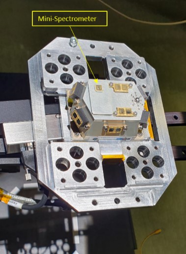
The presence of a mini-spectrometer to observe the sky is an improvement compared with the previous radiometers. The use of a lightweight, low-power and, a COTS technology (commercial-of-the-shelf), opens up a large number of possibilities and functionalities, despite the needed of qualify, verify and calibrate the device under mission-specific requirements.
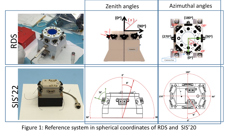
This mini-spectrometer has a working wavelength range between 340-780 nm with a field of view mask of 45° pointing to the zenith. According to the manufacturer, the mini-spectrometer has a spectral resolution of 15 nm and it is composed of 256 pixels, in addition, it has been included an internal PT1000 for monitoring the temperature.
Moreover, there is another mini-spectrometer inside the SIS, working in dark conditions to obtain the dark signal, allowing to subtract the signal from the uncovered one. Additionally, this device will be used as a monitor of the displacement damage of the system.
- Optical Calibration Procedure
The method for the optical calibration is based on the spectro-radiometric transfer from a standard lamp to a standard detector in well-controlled laboratory conditions. The instrument provides a number of ‘counts’ proportional to the photocurrent.
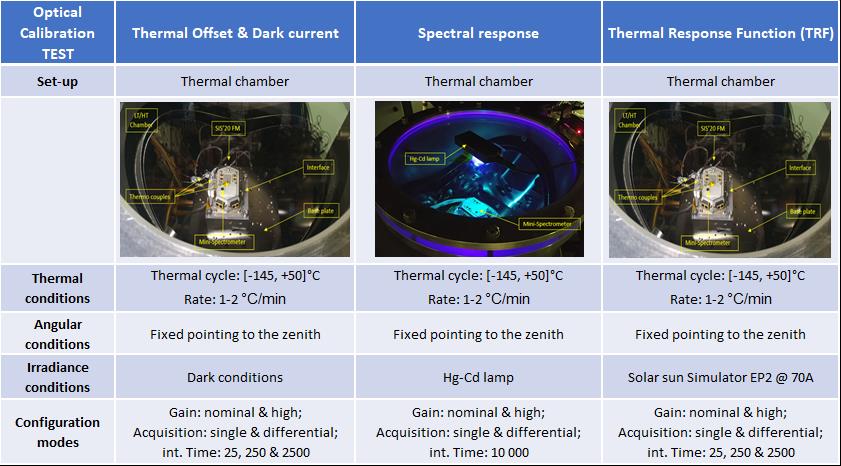
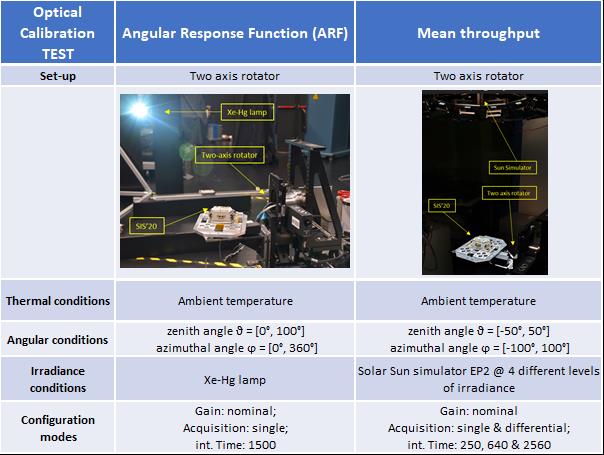
The calibration procedure includes different tests based on the mini-spectrometer main dependances as the thermal offset and dark current effect depending on the temperature, the thermal response (TRF), the spectral dependances, the angular response (ARF) depending on the angle of the incident light and, the main throughput (RSun) of the device, which depends on the irradiance level under normal incidence.
The SIS instrument has been calibrated at INTA facilities by using different optical ground support equipment, based on standard light sources as:
- Solar sun simulators: class A with respect to the spectral distribution, uniformity and temporal stability of irradiance.
- Specific discrete lamps as Hg-Cd and He-Ne, with similar spectrum emission as the mini-spectrometer under study.
- Optical neutral calibrated filters, to reduce the optical power irradiance from AM0 to a lower level, F50 and F35, with a transmittance of 50% and 35% respectively.
- Calibrated spectroradiometer, to measure the absolute irradiance spectrum.
Next Figures summarized the main conditions and set up used in each calibration test.
- Discussion and Conclusions
The calibration procedure described has been an improvement with respect the previous ones due to the spectral nature of the mini-spectrometer analyzed. These properties had involved new corrections to have in mind as:
- The spectral response: calibrating the obtained spectrum with a Cd-Hg lamp source allowed to compare the pixel position of the spectrum peaks with a known certificated and calibrated spectrum.
- Spectral TRF: it was needed a correction of the thermal displacement on the position of the pixels because of variations of the diffraction grating.
The mathematical model used in the analysis to describe each of the calibration performances has been an achievement due to the residual, precision and accuracy obtained when the experimental data was evaluated:
- Each equation includes all the operation and acquisition modes, the gain configurations and the integration time values to evaluate all possible scenarios.
- Thermal offset and ARF were composed by physical equation models.
It has been possible to characterize the signal in dark conditions with an uncertainty on full scale less than 1 % under ‘single’ and less than 0.01% in the ‘differential’ modes. The spectral shift has been found around 5 nm for the entire thermal range, between -145º C and 50º C, and has been characterized with an uncertainty less than 2 %. The spectral responsivity has been calibrated with a precision and uncertainty below 0.1 % and 7% respectively.
- References
[1] Jiménez,J.J., J Álvarez,F., Gonzalez-Guerrero,M. et al. Calibration OGSEs for multichannel radiometers for Mars atmosphere studies. CEAS Space J10,127–145(2018).https://doi.org/10.1007/s12567-018-0194-8.
[2] Ápestigue,V., Gonzalo,A., Jiménez,J.J., et al. Radiation and Dust Sensor for Mars Environmental Dynamic Analyzer Onboard M2020Rover. Sensors2022,22(8),2907;https://doi.org/10.3390/s22082907
How to cite: García-Menéndez, E., Jiménez Martín, J. J., González-Guerrero, M., De Mingo Martín, J. R., Martínez Oter, J., Martín Beamonte, I., Montalvo Chacón, S., Rivas Abalo, J., Serrano Santos, F., and Arruego Rodríguez, I.: Optical Calibration procedure and results of the mini-spectrometer from the Solar Irradiance Sensor (SIS) radiometer for the ExoMars’22 mission, Europlanet Science Congress 2022, Granada, Spain, 18–23 Sep 2022, EPSC2022-1001, https://doi.org/10.5194/epsc2022-1001, 2022.
Introduction
INTA Payloads and Space Science Department is involved in several scientific missions to Mars, developing solar irradiance sensors (SIS), name given for these devices which are multispectral multichannel radiometers for atmosphere studies.
Two SIS were manufactured before 2015: MetSIS (a radiometer intended to be launched onboard the for the Mars MetNet Precurssor Penetrator [1]) and the DREAMS-SIS for the ill-fated Shiaparelli lander of the ExoMars’16 mission ([2]-[5])
Two radiometers have been developed recently: the Radiation and Dust Sensor(RDS) for Mars2020 Perseverance ([6]-[7]) and the SIS'22 for Exomars 2022 Kazachok lander [8]. RDS is currently working on Mars [9]-[10].
Either RDS and SIS’22 combine optical detectors which point to the zenith (top channels) and to the horizon, with an elevation of 20 degrees respect to the horizontality, and distributed in the azimuth (lateral channels).

Innovation
The optical response can be expressed with the following expression, which accounts for the mathematical model used in their calibration [11] and [13] to [19]:

This equation has four parameters:
- ARF, Angular Response Function. This term represents the influence on the channel response of the angular coordinates of the light source respect to every optical detector
- TRF, Thermal Response Function. It deals with the effect of the detector temperature in its response to a luminous source
- R, responsivity or mean throughput of the optical detector in the range between the wavelengths l1 and l2, to which the channel is sensitive.
- Offset, related to the signal of the photodetectors in dark conditions and to the effects on the conditioning electronics on the signal level.
The model works under the assumption that angle, temperature, responsivity are independent variables [11]. Hence, four independent characterizations are run in order to get these four parameters:
- Offset calibration: In dark conditions, the temperature is swept to cover the entire thermal range.
- Optical Thermal calibration (TRF): the optical power and the angle of incidence of the light are fixed and only the temperature is made to change.
- Angular calibration (ARF): the optical power and the temperature are fixed and only the light incidence angle is made to change.
- Mean throughput measurement (RSun): the optical power lamp is excited in several steps, increasing irradiance from a low level to a high one at room temperature with the light at normal incidence over each optical channel.
Some of the changes had to be introduced for RDS and SIS’22 calibrations, as new challenges had to be overcome respect to the requirements imposed on the DREAMS SIS. These additional demands had an important impact on the calibration:
- Narrower FoVs. The alignment is more critical and a new ARF model was implemented.
- UV channels: different light sources, with a higher signal in the UV, were used.
- Some channels were designed to detect only diffuse light: light intensity of the solar simulation had to be reduced drastically for the particular calibration of those channels.
- Having six and eight lateral channels instead of three entailed a higher complexity in the angular sweep and mean throughput alignment.
In the particular case of the RDS, having completed the calibration and field campaigns in representative Martian analogous, the first measurements obtained directly from Mars showed some mismatches with the calibration model. A refinement of the analyses was performed to reduce these discrepancies and to improve the lowest measurable signal level:
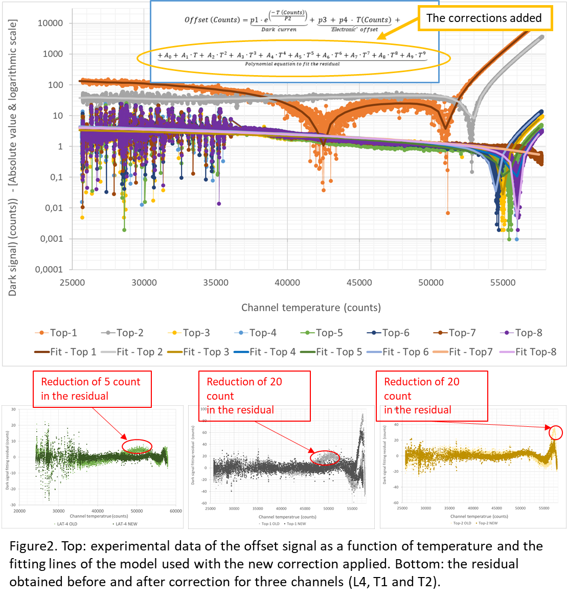
- Corrections were introduced in the offset model in order to reduce the discrepancy between the experimental points and the fitting (the residual) by up to 20 counts at a full scale of 65535 (0.05%). That becomes essential in very low light conditions and certain temperatures. It can be as much as a 50 % of the signal. However, such temperatures have never been reached in RDS and even less at times of low illumination (sunrise or sunset).
- A spectral correction below 2 % was introduced to calculate the mean responsivity of the sun simulator. This lamp source produces a spectrum which is very similar to that of the sun outside the atmosphere. A correction to fit its radiance to a perfect solar spectrum had not been used before.
- The main upgrade comes from the modelization of the ARF, its “blocking zone” and the effects of the dust in Mars.
ARF
The angular sensor response (ARF) can be divided into 3 regions: the Field of View (FoV), the blocking and the transition regions. The blocking zone was found in early tests to be smaller than 1e-4(1e-2%) and was considered negligible.
The ARF model was implemented firstly with a function with two terms and it was valid only for the FoV and the transition regions. Blocking regions were found to be non negligible, so a new term was added to account for the sensitivity of the optical channels in those areas, though the experimental data are limited by the noise of the channels noise, in the order of 3e-4 (3e-2%).
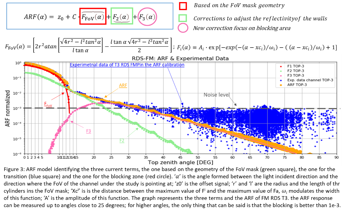
Despite this refinement, the retrieval models did not match the observations yet. For this reason, a characterization test of the blocking region was performed using the Flight Spare Model (FSM) in a heliostat. That test showed that the effect of the blocking region i is actually lower than 1e-5 counts, while the data from Mars was showing values in the order of 5e-4 (5e-2%).
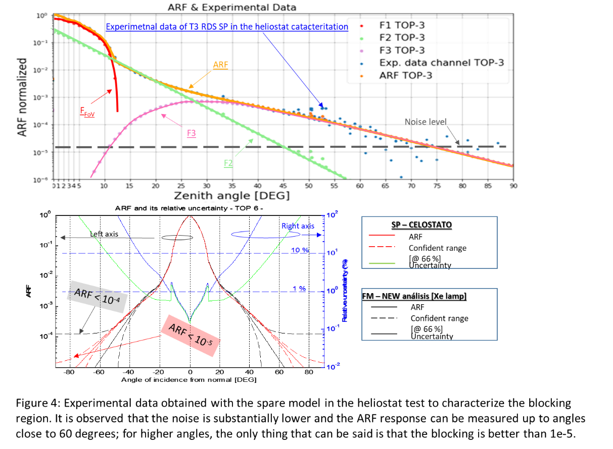
Finally, a test was performed with the FSM unit to evaluate the effect of the deposited dust. The dust in the RDS structure increased the signal in the blocking zone of the optical channels in several orders of magnitude. Therefore, in order to determine the signal in this areas, it it is necessary to estimate the amount of dust deposited on the unit.
Conclusion
Improvements have been introduced in the process and analysis of the calibration of the multichannel radiometers manufactured by INTA for Mars missions. Peculiarities of the last developed instruments (RDS and SIS'22) and discrepancies between the results obtained in field campaigns and the actual measurements being obtained in Mars have been the reason for the upgrade of the calibration procedures and the analysis of their results.
How to cite: Jiménez Martín, J. J., García-Menéndez, E., Álvarez Ríos, F. J., Gonzalez-Guerrero Bartolomé, M., Apástigue Palacios, V., De Mingo Martin, J. R., Martinez Oter, J., Martín Beamonte, I., Montalvo Chacon, S., Rivas Abalo, J., Serrano Santos, F., Toledo Carrasco, D., and Arruego Rodríguez, I.: Calibration of RDS of Mars 2020 and SIS’22 of Exomars 2022 for Mars exploration, Europlanet Science Congress 2022, Granada, Spain, 18–23 Sep 2022, EPSC2022-1122, https://doi.org/10.5194/epsc2022-1122, 2022.
Introduction: The camera performance for space missions should be verified before flight. Exposure times with the expected fluxes should be planned, resulting signal-to-noise ratios (SNR) computed, and the overall image quality evaluated. This can be done in a specialized laboratory but having a quick simulation tool to help the design in early phase would be an asset.
We have developed a software based on Blender and Python post-processing for the abovementioned purpose. The software [1] is used with the ASPECT hyperspectral camera (Milani CubeSat, ESA’s Hera mission), the HyperScout hyperspectral camera (Hera mission), and the MIRMIS hyperspectral camera unit (ESA’s Comet Interceptor mission).
Modeling and rendering an asteroid or a comet nucleus: Blender is an open-source rendering software that is widely used in many fields [2]. Capabilities in modeling the 3D geometry and rendering the result makes it also suitable for simulating how an asteroid or a comet nucleus would appear when imaged.
For camera testing purposes, the geometry of the target does not need to be completely correct. It is sufficient that the overall size and shape matches the target, and the surface roughness and boulder distribution are representative. Blender has functions for introducing procedural geometric features randomly on the underlying shape, and we use this to introduce boulders of different sizes on the target. For the overall target shape, either low-resolution models derived from lightcurve or radar observations or high-resolution shape models from previous missions can be used, such as the models for Bennu, Ryugu, or 67P/Churyumov–Gerasi¬menko (see Fig. 1).
We have implemented some common photometric models for the surface material in Blender. Blender has some limitations when compared to other ray-tracers, namely it does not really support custom scattering laws to be implemented. The internal ray-tracing loop employs only Blender’s internal shaders, i.e., scattering laws for a surface element. In other words, one can implement any phase function depending only on the phase angle in Blender, but not disk function that would depend on the incident and scattering directions.
Fortunately, Blender’s internal shaders include Lommel-Seeliger (‘volume scatter’ in Blender) and Lambertian (‘diffuse BSDF’), and one can also mix these, which covers already the common disk functions for dark and bright surfaces quite well. For phase functions we have implemented the exponential-polynomial, linear-magnitude, and ROLO functions as shown in [3]. By combining the disk and the phase functions we can implement Lommel-Seeliger, ROLO, McEwen, and Lambert photometric functions for the target.
The Blender part of our software is outputting ‘ideal’ noiseless images with a given observing geometry, camera field-of-view, detector resolution, and surface albedo. Our post-processing step subsequently introduces the effects originating from the camera and the detector physical capabilities.
Camera performance simulation: The images can be converted to real physical units (I/F, Watts, photons, electron counts on CCD). While the RGB channel values in the Blender images have arbitrary units and scale, one can render a Lambertian disk at backscattering with the same illumination intensity and target-camera distance as in the actual object image. This calibration procedure will give us I/F conversion from the RGB values. Considering the target’s distance to the Sun we can further convert these into radiant flux in Watts.
If we are dealing with a spectral instrument, we need to have a spectral image/datacube. Currently we are not changing the parameters of the photometric function with the wavelength. This implies that the received flux is only linearly dependent on the wavelength-dependent albedo of the target, and that we can just multiply one rendered image with the normalized spectra of the target’s surface material for a spectral datacube.
With spectral flux for each image pixel, we can apply the transmission of the camera optics and the spectral filter (i.e., the Fabry-Perót interferometer in ASPECT and MIRMIS cameras). Watts can be converted into photon counts for each wavelength, and finally the detector quantum efficiency curve can be used to achieve electron elementary charges at the detector.
Once the electron charges per time unit on the detector has been solved, we can introduce a reasonable dark field pattern, dark current noise (Poisson), readout noise (Gaussian), and photon shot noise (Poisson) for a given exposure time. This will give us the final, simulated camera image or a hyperspectral datacube of the target, together with the SNR estimate.
Discussion: The SSO object simulated imaging and camera performance tool can be used to produce expected camera data, with realistic noise, for space mission and instrument design. Especially with (hyper)spectral cameras this tool can be used to verify how different spectral and/or spatial details could be resolved with certain exposures, noise levels, and optics/camera transmissions.
We have started with application to atmosphereless, relatively homogeneous targets such as an asteroid or a comet nucleus. Variability to surface properties (local albedo or color, for example) can be introduced using Blender’s procedural modeling tools. Simple atmospheres and comet gas/dust environments could be added in the future. To some extent, this is what is done in the SISPO project [4]. We verify our results against the NASA Planetary Spectrum Generator [5]. For visualizing views to an asteroid or a comet with a given spacecraft flight path, possibly given with a SPICE kernel, we acknowledge the shapeViewer [6] tool.
Figure: Blender-visualization of the high-resolution shape model of asteroid Ryugu with added boulders on the surface.
References: [1] Git project for the Blender/Python imaging simulations. https://bitbucket.org/planetarysystemresearch/workspace/projects/SSO_PHOTOMETRY. [2] Blender software, https://www.blender.org/. [3] Golish D. R. et al. (2021) Icarus, 357, 113724. [4] Pajusalu M. et al. (2021) arXiv, astro-ph.IM, 2105.06771. [5] NASA Planetary Spectrum Generator, https://psg.gsfc.nasa.gov/ [6] Vincent J.-B. (2014) ACM conference, Helsinki.
How to cite: Penttilä, A., Palos, M. F., Näsilä, A., and Kohout, T.: Blender modeling and simulation testbed for solar system object imaging and camera performance, Europlanet Science Congress 2022, Granada, Spain, 18–23 Sep 2022, EPSC2022-788, https://doi.org/10.5194/epsc2022-788, 2022.
Mutual impedance experiments are in situ space plasma diagnostic techniques for the determination of characteristic plasma parameters, such as the plasma density and the electron temperature. These electric experiments rely on the coupling between two emitting and two receiving antennas embedded in the plasma to be diagnosed.
Different versions of mutual impedance instruments are included in the scientific payload of past, present and future exploratory planetary space missions, such as the RPC-MIP instrument onboard the Rosetta spacecraft that explored the cometary environment of comet 67P/CG, the PWI/AM2P experiment onboard the Mio spacecraft of the BepiColombo mission that will investigate the Hermean environment, the RPWI/MIME experiment onboard the JUICE spacecraft that will characterize the magnetosphere and ionosphere of Ganymede, and the DFP/COMPLIMENT instrument onboard the Comet Interceptor spacecraft that will map the ionized environment of a pristine comet and its interaction with the solar wind.
The next step in planetary exploration shall rely on small satellite platforms and the concept of multi-point measurements missions. In particular, by mapping the investigated plasma environment, multi-point measurements shall improve our understanding of the investigated physical phenomena by enabling the distinction between spatial and time dependent variations, a distinction that is not possible with current single-point measurements configurations.
In this context, mutual impedance instruments are now being adapted to better fit small satellite platforms. Instrumental development efforts are put into various and complementary directions. First, we are increasing the signal emission amplitude of the mutual impedance instrument in order to improve the signal-to-noise ratio of the measurements and to relax EMC (i.e. electromagnetic compatibility) constraints on the small satellite platform while maintaining robust plasma density and electron temperature diagnostic performances. Second, we are optimizing the time-resolution of the instrument to facilitate the coupling of mutual impedance experiments with different plasma experiments, such as the Quasi-Thermal Noise and the Langmuir Probe experiments, all using the same electric sensors to perform their measurements. Indeed, coupling between different experiments and sharing of sensors is crucial for nanosatellite applications, where the limited mass and volume strongly constrain the design of the payload instrumentation.
To reach such goals, we use two complementary tools. Our first tool is a numerical 1D-1V full-kinetic electrostatic Vlasov-Poisson model that enables to simulate the propagation of electric perturbations generated in the plasma by mutual impedance experiments and address both the effect of nonlinearities and inhomogeneities in the instrumental response. Our second tool is the plasma chamber of CNRS-LPC2E space laboratory (Orléans, France) that enables experimental tests of space plasma instruments and nanosatellites in typical plasma conditions encountered in planetary ionospheres. We use this plasma chamber to test both mutual impedance miniaturized instrument prototypes and new mutual impedance instrumental modes.
The results of our investigation are the following.
First, using our new instrumental model in both linear and non-linear regimes, we identify for the first time the maximum emission amplitude that can be used in mutual impedance experiments without introducing spurious nonlinear perturbations in the plasma and show the robustness of both plasma density and electron temperature diagnostics even when non-linear effects such as wave-wave and wave-particle interactions are triggered in the plasma. We find on optimal threshold of the electric energy injected in the plasma to be smaller than 10% of the electron thermal energy, to be applied to the design of future mutual impedance experiments.
Second, using both our numerical model and the plasma chamber facility, we show that the sensor occupation can be drastically reduced without loss of plasma density diagnostic, thus potentially enabling a significant increase of time resolution for future mutual impedance experiments. This result enables the design of a new mutual impedance instrumental mode, called “chirp mode”, for which the measurement time duration is reduce by a factor 10-100 compared to typical space applications such as the RPC/MIP onboard the Rosetta spacecraft.
These new instrumental developments will be at the basis of significant improvements in the design of future mutual impedance experiments for planetology exploration.
How to cite: Bucciantini, L., Henri, P., Wattieaux, G., and Califano, F.: Instrumental modeling of Mutual Impedance experiments and validation tests in plasma chamber, Europlanet Science Congress 2022, Granada, Spain, 18–23 Sep 2022, EPSC2022-1076, https://doi.org/10.5194/epsc2022-1076, 2022.
- Introduction
In this work, we present the calibration of the NEWTON magnetic susceptometer for in-situ determination of the magnetic susceptibility of planetary surface rocks and regoliths. The susceptometer is based on inductive methods, and its operation does not require of sample preparation or manipulation. Current prototype has demonstrated capabilities for the determination of the complex magnetic susceptibility, i.e. real and imaginary component of the susceptibility [1, 2]. We propose the NEWTON susceptometer for the determination of the complex magnetic susceptibility, to provide valuable information about the regolith and surface rocks in rocky bodies of the solar system, to be used as a selection criterion of rocks for sample return missions or for the in-situ scientific studies of the magnetic properties during planetary missions.
- Calibration of the susceptometer
Due to the design of the instrument and the nature of the available magnetic susceptibility patterns [3], there are not available susceptibility calibration samples traceable to primary patterns with characteristics compatible with this device. The calibration procedure comprises a comparative methodology, consisting in two steps: the manufacture of magnetic susceptibility patterns, to serve as calibration samples of the real and imaginary parts separately for the NEWTON susceptometer; and the comparison of the results from the prototype with those from reference equipment.
The manufactured samples for the calibration of the real component of the magnetic susceptibility were made of ferrite powder diluted in a non-magnetic epoxy resin. Four samples of different mass content in ferrite powder were made, with the following distribution: a sample with 10% (weight %), a sample with 1%, a sample with 0,1% and a sample with 0,03% in ferrite powder. The homogeneity of the distribution of the ferrite powder within the samples was verified with X-ray images.
The imaginary susceptibility calibration samples were constructed using different techniques and comparing the results with other reference equipment. The sample used for calibration is made of 2.5mm diameter steel spheres (rolling bearing balls) distributed in a cubic lattice in a resin matrix providing both isotropic real and imaginary magnetic susceptibility values.
- Environmental testing
The most critical parts of the instrument have been submitted to qualification tests: vibration, thermal-vacuum and outgassing tests, applying the same requirements and test levels of those for the landing Mars mission, Exomars 2022, to demonstrate the capability of the instrument to withstand the interplanetary missions and space conditions.
- Application of the NEWTON susceptometer
The characterization of the complex magnetic susceptibility of rocks is an unexplored tool to constrain the composition, structure and geological history of rocks in surface planetary exploration [4]. The instrument is designed to measure a dynamic range of the real susceptibility from χ’ = 10-4 S.I. to χ’ = 101 S.I. for the real susceptibility, representative values for the rocks of the Earth, Moon and Mars [5, 6, 7]. The imaginary susceptibility measurement procedure has a resolution in the order of χ” = 10-6.
The sensor is suitable to be placed on board rovers, or to be used as a portable device during field campaigns and by astronauts in manned space missions. This sensor provides a great advantage compared to available commercial susceptometers, given that it does not require sample preparation, but only a minimum sample size (~50 x 20 x 20 mm). The current state of the susceptometer prototype consist of a portable device divided in two boxes: the Sensor Box (SB), containing the sensor core; and the Electronics Box (EV) containing the support electronics for the operation of the instrument (Figure 1).
The application of susceptibility measurements during space missions have a potential impact in the surface regolith and rocks characterization. The analysis of the samples from the Apollo missions [4], the characteristics of the Martian magnetic field [5], works in stony meteorites [6], Earth impact areas [7] and Earth analogues [8] highlight the enhancement of the scientific research that in situ magnetic field and magnetic susceptibility measurements provide to the Lunar and Martian exploration.
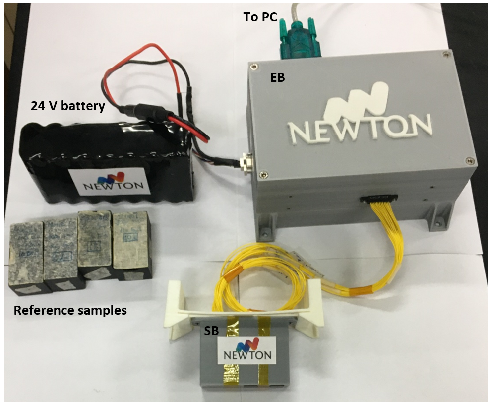
Figure 1. Image of the setup of the NEWTON instrument for in situ measurements during field campaigns, including reference samples for calibration.
Acknowledgement
This work has been funded by the Spanish Programme for Research, Development and Innovation under the grants of references ESP2017-88930-R and PID2020-119208RB-I00: MagAres and MINOTAUR, respectively, as well as the European Union Project NEWTON, of grant agreement 730041.
References
[1] J.L. Mesa et al. Feb. 2022. Submitted to IEEE Trans Instrum Meas.
[2] M. Díaz Michelena et al. 2017, Sensor Actuat A-Phys, vol. 263, pp. 471-479
[3] https://www.nist.gov/mml/materials-science-and-engineering-division/magnetic-moment-and-susceptibility-standard-reference. NIST. Retrieved May 4, 2022.
[4] M.S. Bentley et al. 2009, Planet Space Sci, vol. 57 (12), pp. 1491-1499.
[5] P. Rochette et al. 2006, Astrobiology, vol 6(3), pp. 423-36.
[6] P. Rochette 2010, Earth Planet. Sci. Lett., vol. 292, pp. 383–391.
[7] A. Collareta 2016, Meteorit Planet Sci, vol. 51 (2), pp. 351–371
[8] J. Pati, etl al 2016, Curr Sci India, vol. 111 (3), pp. 535-542.
How to cite: Mesa Uña, J. L., Díaz Michelena, M., and Aroca Hernández-Ros, C.: Calibration of NEWTON Susceptometer for fast and in-situ determination of the complex magnetic susceptibility., Europlanet Science Congress 2022, Granada, Spain, 18–23 Sep 2022, EPSC2022-864, https://doi.org/10.5194/epsc2022-864, 2022.
Please decide on your access
Please use the buttons below to download the presentation materials or to visit the external website where the presentation is linked. Regarding the external link, please note that Copernicus Meetings cannot accept any liability for the content and the website you will visit.
Forward to presentation link
You are going to open an external link to the presentation as indicated by the authors. Copernicus Meetings cannot accept any liability for the content and the website you will visit.
We are sorry, but presentations are only available for users who registered for the conference. Thank you.
Please decide on your access
Please use the buttons below to download the presentation materials or to visit the external website where the presentation is linked. Regarding the external link, please note that Copernicus Meetings cannot accept any liability for the content and the website you will visit.
Forward to session asset
You are going to open an external link to the asset as indicated by the session. Copernicus Meetings cannot accept any liability for the content and the website you will visit.
We are sorry, but presentations are only available for users who registered for the conference. Thank you.