
Antenna-Array Radar Applications in Chinese CE-5 and CE-6 Missions
 1,2,1,1,2
- 1National Astronomical Observatories, Chinese Academy of Science, China (suyan@nao.cas.cn)
- 2School of Astronomy and Space Science, University of Chinese Academy of Sciences
Ground Penetrating Radar (GPR) technology has been extensively applied in Chinese lunar exploration. The first attempt to survey the Moon’s subsurface using a GPR onboard a rover was made during the Chang’E-3 (CE-3) mission, which featured dual-frequency channels (G.Y. Fang, et al., 2014). The identical Lunar Penetrating Radar used in the CE-3 mission, was successfully deployed during the Chang’E-4 (CE-4) mission. It effectively explored the subsurface structure to a depth of ~ 40m within the South Pole-Aitken Basin, located on the farside of the moon (C.L. Li, et al., 2020).
Another remarkable design is the GPR of the Chang'e-5 (CE-5) mission. Because GPR for the CE-5 mission was mounted on the lander rather than on the rover, it was necessary to break the conventional design pattern. To address this challenge, an antenna-array radar was deployed,making the first application in the deep space mission. The array radar is named the Lunar Regolith Penetrating Radar (LRPR). The LRPR comprises a controller, a pair of transmitter and receiver, a distribution unit, a cable assembly, and an antenna array, which consists of 12 ultra-wideband time-domain antennas. As shown in Fig.1, these antennas are mounted asymmetrically around the drilling system as the bottom of the lander. Operating under a multiview/multistatic configuration, one antenna transmits while the other 11 antennas receive backscattered echoes during one measurement period(Y.X. Li, et al., 2019). Such configuration allows for the collection of 132 trace data. The complete measurement stage for the 12 transmitting antennas lasts ~18 minutes.
The Chinese CE-6 mission was successfully launched on May 3rd, 2024. The CE-6 landing zone has been selected to lie within the lunar farside South Pole–Aitken (SPA) basin in the southern part of the Apollo basin (150–158° W, 41–45° S), a site that provides access to a diversity of SPA material (see Fig.3). The CE-6 lander also carries the same radar instrument used in CE-5 mission, the LRPR. The primary objective of the LRPR is to investigate the interior structure of the local regolith and identify potential underground hazards that could pose risks to the drilling activity. Understanding the interior structures of lunar regolith is crucial for comprehending surface resulting from processes, such as impact cratering. Local stratigraphy provides the contextual information for interpreting the origin of samples collected from both the surface and the drilling core.
In this report, we will detail the signal calibration, data processing procedures of the array radar, and present the results obtained from the CE-5 LRPR. The CE-6 LRPR is expected to commence operations by the end of May. If successful, we will provide updates on the new results obtained. Given that the scheduled CE-6 landing site is situated within the most prominent SPA basin(see Fig.3), we are hopeful that the LRPR will unveil new discoveries.
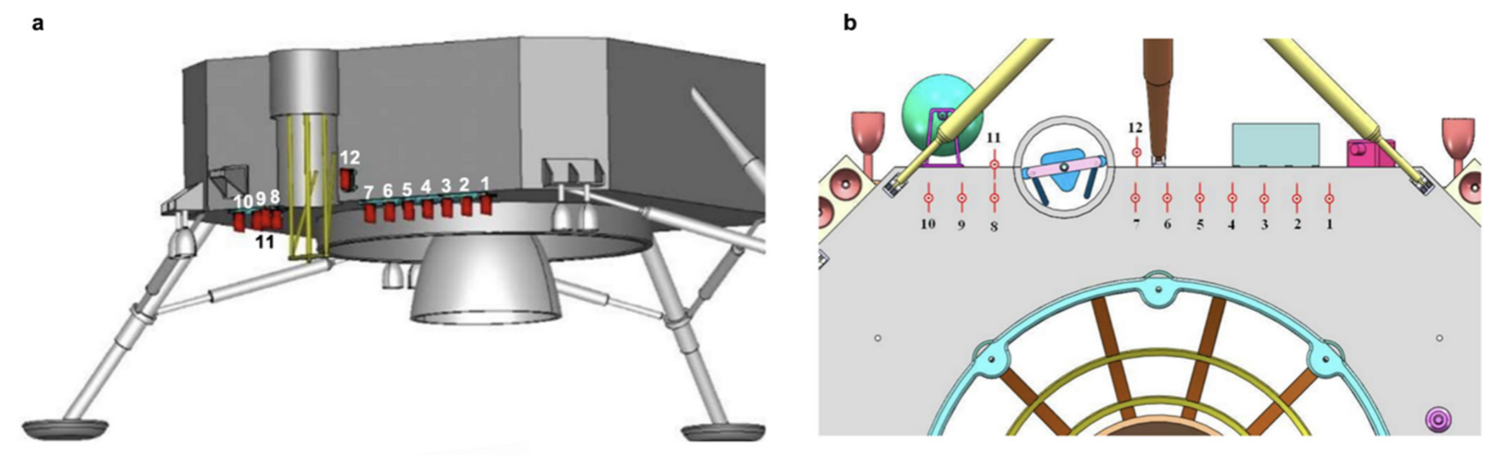
Fig.1 Layout of the LRPR antennas around the drilling core onboard the CE-5 and CE-6 lander. (a) Side view and (b) bottom view of the antenna array. Antennas #1–#10 are aligned at the bottom of the CE-5 lander, while antennas #11 and #12 are installed separately.
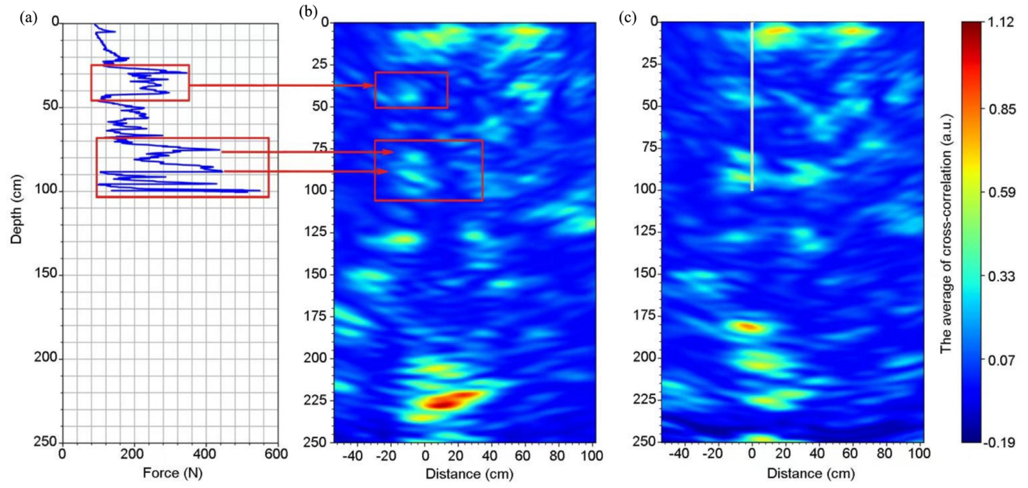
Fig. 2 LRPR observations at the CE-5 drill-sampling site. (a) Variation of the drill bit force along the depths. The horizontal axis is force (N). The drilling system collected the rotation angle of a photoelectric encoder each second; then, this angle was converted to the distance of the drilling core movement to obtain the depth of the bit position. (b) LRPR radar image before drilling. The vertical axis is depth (cm), and zero-depth corresponds to the interface air/soil. The horizontal axis is the distance from the drill bit (cm). The red color represents high reflectivity (large electromagnetic contrast) and blue is low reflectivity (small electromagnetic contrast). (c) Radar image after drilling with the same processing method as that used in (b).
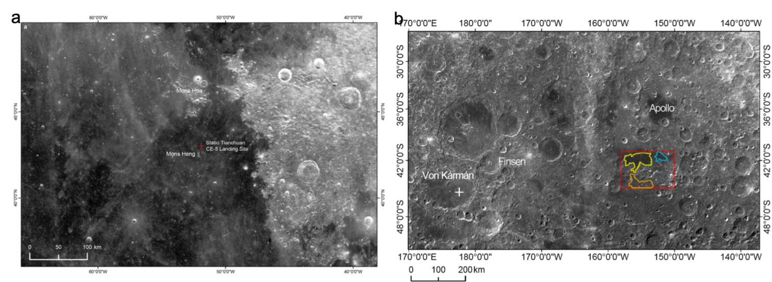
Fig.3 The landing site of CE-5 (a) and the schedule landing site of CE-6 (b). (a) The CE-5 probe landed on the lunar surface at 43.06 N, 51.92 W, a young and flat mare surface at the northeast Oceanus Procellarum. (b) The scheduled CE-6 landing zone is located in the interior of the SPA basin, along the southern rim of the Apollo basin.
References
- -Y. Fang, B. Zhou, Y.-C. Ji, Q.-Y. Zhang, S.-X. Shen, Y.-X. Li, H.-F. Guan, C.-J. Tang, Y.-Z. Gao, W. Lu, S.-B. Ye, H.-D. Han, J. Zheng, S.-Z. Wang, Lunar penetrating radar onboard the Chang’e-3 mission. Res. Astron. Astrophys. 14, 1607–1622, 2014.
- Li et al., “The Moon’s farside shallow subsurface structure unveiled by Chang’E-4 Lunar Penetrating Radar,” Sci Adv, vol. 6, no. 9, p. eaay6898, 2020.
- Li, W. Lu, G. Fang, B. Zhou, and S. Shen, “Performance verification of lunar regolith penetrating array radar of Chang’E-5 mission,” Adv. Space Res., vol. 63, pp. 2267–2278, Apr. 2019.
- Su et al., Hyperfine Structure of Regolith Unveiled by Chang’E-5 Lunar Regolith Penetrating Radar, IEEE Transactions on Geoscience and Remote Sensing, VOL. 60, 2022
How to cite: Su, Y., Li, C., Liu, J., Zhu, X., Liu, B., Liu, D., and Zhang, Z.: Antenna-Array Radar Applications in Chinese CE-5 and CE-6 Missions, Europlanet Science Congress 2024, Berlin, Germany, 8–13 Sep 2024, EPSC2024-239, https://doi.org/10.5194/epsc2024-239, 2024.