
Shape and Albedo from Shading with Planetary Flyby Images of Mercury and the Moon
 1,2,3,1,1,4,6,7
- 1Image Analysis Group, TU Dortmund University, Dortmund, Germany
- 2Faculty of Physics and Electrical Engineering, University of Bremen, Bremen, Germany
- 3Institute of Space Systems, German Aerospace Center (DLR), Bremen, Germany
- 4Istituto di Astrofisica e Planetologia Spaziali (INAF), Rome, Italy
- 5ESAC, ESA, Madrid, Spain
- 6ESTEC, ESA, Noordwijk, Netherlands
- 7Central Staff Association, ESA, Paris, France
Introduction
Surface reconstruction of planetary bodies such as the Moon and Mercury is crucial for geomorphological analysis, reflectance normalization, thermal modeling, rover landing site planning, and outreach activities. Stereo algorithms and Shape-and-Albedo-from-Shading (SAfS) are well-established methods for planetary 3D reconstruction. The current state-of-the-art combines both methods. SAfS refines the surface slopes of a stereo digital elevation model (DEM) and typically yields 3D models at image resolution [1,2,3,4,5,6]. This approach is generally well-validated for scientifically calibrated instruments that observe the planetary body under favorable conditions. However, the limits of SAfS still need to be explored. This work applied the SAfS algorithm to planetary flyby images acquired with uncalibrated off-the-shelf cameras. We qualitatively and quantitatively assessed the algorithm's performance and found the method robust even under these challenging conditions.
Methods
We considered two images: First, a flyby image of Mercury (Figure 1, left), which was obtained with a monitoring camera during BepiColombo’s third flyby, and second, a flyby image of the Moon captured by a GoPro during the Artemis I mission (Figure 1, right). In both cases, off-the-shelf cameras without a proper radiometric calibration routine were used instead of scientific instruments. Therefore, it was necessary to calibrate the images before applying the SAfS algorithm. For calibration, we estimated a reflectance image of the region of interest with Hapke parameters from [7] to establish a relationship between the digital number output of the camera and the physical radiances. The resulting Mercury flyby DEM was evaluated qualitatively, compared to MDIS WAC images [8]. The lunar flyby DEM was compared to the SLDEM2015 (60-100 m/pixel) [9], which serves as a ground truth.
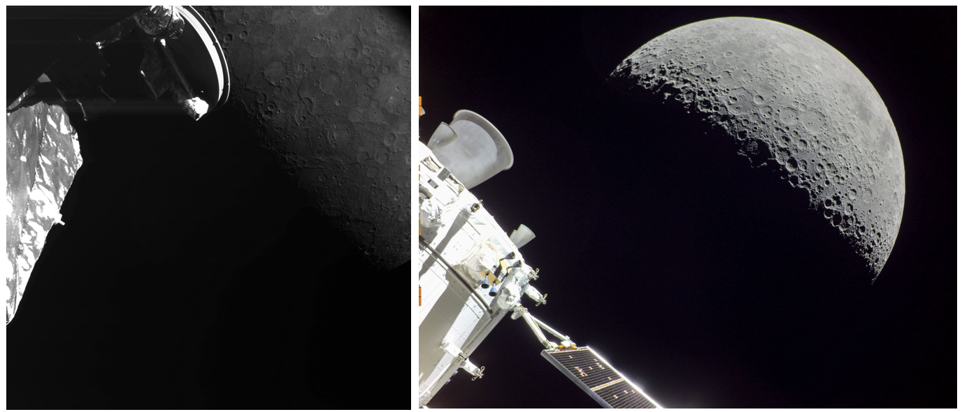 Figure 1. Left: Flyby image from the BepiColombo mission [10]. Right: Flyby image from the Artemis I mission [11].
Results
Figure 2 shows the color-coded SAfS DEM for the BepiColombo image. We found that the algorithm successfully reconstructed the surface in the center of the image but struggled with the more extremely illuminated sections at the edges. It is obvious that the algorithm reconstructed some details that are not visible in the input DEM and hence improved the resolution. Figure 3 compares a grey-scale representation of the SAfS DEM with MDIS WAC image EW0251718878F. Small craters in Izquierdo (the crater in the right half of the marked section), a few kilometers in diameter, become especially visible. Figure 4 shows the marked section in more detail. Due to the lack of high-resolution ground truth, a detailed algorithm evaluation was not possible for this image.
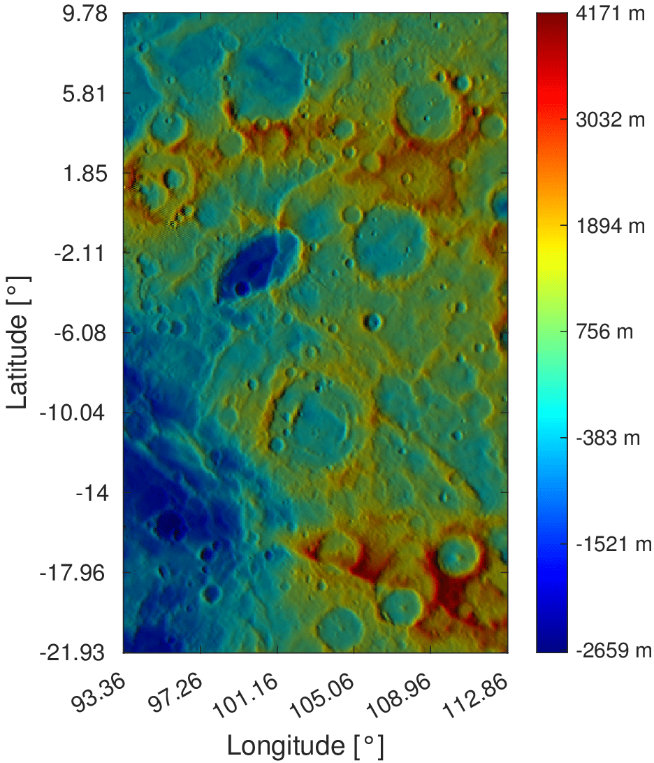
Figure 2. Color-coded presentation of the reconstructed SAfS DEM from the BepiColombo image.
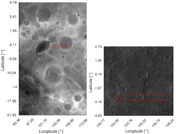
Figure 3. Left: grey scale reconstructed SAfS DEM from the BepiColombo image. Right: wide-angle camera (WAC) image from MDIS [8]. The marked image section was evaluated in more detail (Fig. 4).
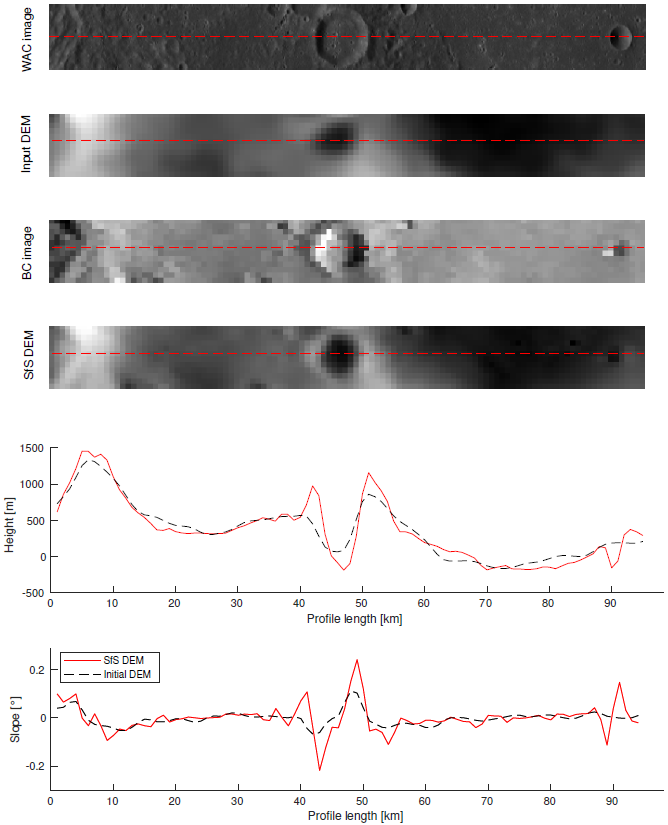
Figure 4. Comparison of WAC image, input DEM, BepiColombo (BC) image and SAfS DEM. Below the images are the height and slope of the profile (red dashed line).
However, the ground truth evaluation with the Artemis I image gives a quantitative measure under comparable conditions. Figure 5 shows the color-coded SAfS DEM of a region of interest (ROI) reconstructed from the flyby image. The results for the Artemis I image for all ROIs were of high quality. Figure 6 shows the elevation profile indicated by the dashed line in Figure 5. The algorithm refines the low-frequency initial DEM (dashed line), yielding a SAfS DEM (red line), which closely resembles the ground truth DEM (black line). The vertical RMSE between the reconstructed DEM and the ground truth is 523 m, lower than the pixel size of approximately 1500 m. However, there were inaccuracies near the ROIs’ edges, and a preferred direction aligned with the illumination direction became visible.
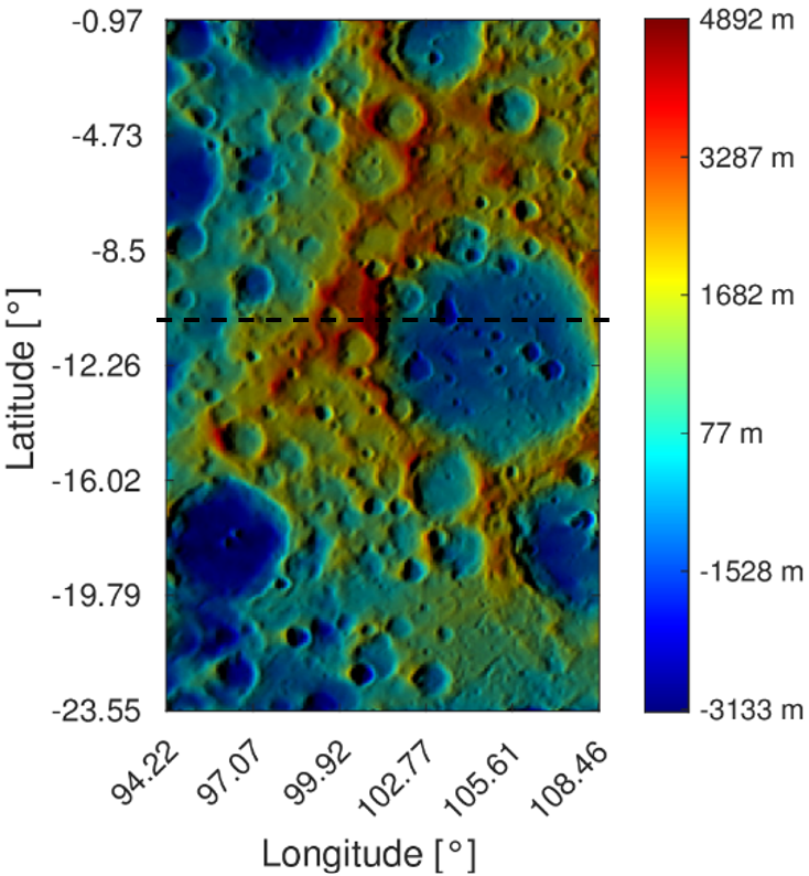
Figure 5. Color-coded presentation of the reconstructed SAfS DEM from the Artemis image. The black dashed line marks the profile that was analyzed in detail (see Fig. 6).

Figure 6. Height profile of a selected terrain profile (see black dashed line in Fig. 5). Red line: DEM generated with the SAfS algorithm. Black line: Ground truth DEM. Dashed line: Initial DEM (input for the SAfS algorithm).
Conclusion
In conclusion, it is possible to obtain sharp results by applying our SAfS framework to flyby images. Both results show that, despite the challenging conditions, the SAfS algorithm could reconstruct the surface up to image resolution and increase the level of detail of the input DEM. The quality differences between the two images can mainly be attributed to the (spatial) resolution of the original images and the oblique illumination direction. Usually, the image center is distortion-free, and the illumination geometry is best suited for SAfS. We found that the surface reconstruction at the edge of the image is also possible, but the quality decreases significantly. All in all, our flyby-derived DEMs are accurate, and a previous version has been used for ESA outreach activities, similar to [12]:
https://www.esa.int/Science_Exploration/Space_Science/BepiColombo/BepiColombo_s_third_Mercury_flyby_the_movie
References
[1] A. Grumpe, F. Belkhir, C. Wöhler. Advances in Space Research, 53(12):1735–1767, 2014.
[2] C. Jiang, S. Douté, B. Luo, L. Zhang, P&RS,130, 2017
[3] O. Alexandrov, R. Beyer. Earth and Space Science, 5, 2018
[4] B. Wu, W. C. Liu, A. Grumpe, C. Wöhler. P&RS, 140, 2018
[5] M. Tenthoff, K. Wohlfarth, C. Wöhler. Remote Sensing, 12(23), 2020.
[6] M. Hess, M. Tenthoff, K. Wohlfarth, and C. Wöhler. Journal of Imaging, 8(6), 2022.
[7] J. Warell, Icarus, 167, 2,2004
[8] Hawkins, S. Edward, et al. Space Science Reviews 131 (2007): 247-338.
[9] M.K. Barker, E. Mazarico, G.A. Neumann, M.T. Zuber, J. Haruyama, D.E. Smith, Icarus, 273, 2016.
[10] ESA. Planetary science archive.2023.
https://archives.esac.esa.int/psa/#!Image%20View/MCAM=instrument, accessed 10th May 2024
[11] NASA. flickr, 2022,
https://www.flickr.com/photos/nasa2explore/52547180935/in/album-72177720303788800/, accessed 10th May 2024
[12] K. Wohlfarth, M. Tenthoff, J. Wright, V. Galluzzi, C. Wöhler, H. Hiesinger, J. Helbert, J. Zender, J. Beckhoff. MExAG Annual Meeting, 02.2023
How to cite: Krüll, I., Wohlfarth, K., Tenthoff, M., Wöhler, C., Galluzzi, V., Wright, J., Benkhoff, J., and Zender, J.: Shape and Albedo from Shading with Planetary Flyby Images of Mercury and the Moon, Europlanet Science Congress 2024, Berlin, Germany, 8–13 Sep 2024, EPSC2024-247, https://doi.org/10.5194/epsc2024-247, 2024.