
 1,1,2,
- 1Département de Géomatique Appliquée, Université de Sherbrooke, Sherbrooke, Canada (frederic.diotte@usherbrooke.ca)
- 2Centre for Terrestrial and Planetary Exploration (C-TAPE), University of Winnipeg, Winnipeg, Canada
- 3Canadensys Aerospace Corporation, Bolton, Canada
- 4Canadian Space Agency, Saint-Hubert, Canada
- 5Department of Earth Sciences, University of Western Ontario, London, Canada
Introduction
The Canadian Lunar Rover hosted a suite of instruments that included the MultiSpectral Imager (MSI), a panchromatic camera developed by CanadenSys Aerospace to characterize regolith and rocks within 1 m of the rover. MSI is meant to acquire multispectral imagery by actively illuminating the surface with six pairs of LEDs spanning the 365–940 nm range, enabling analysis of the microscale texture, structure and mineralogical composition at the lunar surface.
Photogrammetric techniques have been applied to evaluate surface morphology from in situ images collected on the Moon (e.g., [1–3]). With a nominal ground sample distance of 50 µm at its optimal focal distance, MSI images could be used to reconstruct microscale 3D models along a rover’s traverse. The standard approach for 3D modelling using monocular images is structure-from-motion, which also requires large volumes of images acquired from multiple perspectives of a target area. In the context of planetary robotic operations, this would involve significant dedicated rover motion, time, and data bandwidth. Alternatively, a 3D model could be reconstructed from MSI images collected from only two imaging stations using stereophotogrammetry. By registering complementary imagery from other onboard cameras across the same stations, the known camera baseline among LRM instruments can be leveraged to solve for MSI camera poses.
Here we evaluate MSI’s capability to produce microscale point clouds under realistic rover operational conditions by leveraging the known geometric relationship between each imager.
Despite the official cancellation of the mission in March 2026, the capabilities developed to date remain applicable to scientific objectives using similar instrumentation on other robotic missions.
Imaging campaign
A science imaging campaign was conducted with the engineering model (fig. 1) of the rover in October 2025 at the Canadian Space Agency. We integrated 56 images taken by rover cameras of the Lunar Unstructured Scanning Rig (LUSR, shown in fig. 1 and fig. 2), a lunar model designed by CSA to characterize the accuracy of 3D sensors. Cameras included MSI; StereoCam (SCAM), a pair of RGB cameras mounted near the top of the rover with overlapping fields of view; HazCam, a forward- and downward-looking RGB hazard camera with a wide field of view; and NISA-1000, a forward-looking camera mounted near the top of the rover and equipped with a long-pass near infrared filter.
Camera poses were directed toward a region of 50 × 50 cm situated at one corner of the LUSR. The rover was positioned at 15 locations along four radial transects around the selected corner, imaging the target with each camera for which the LUSR was within the field of view (fig. 3).
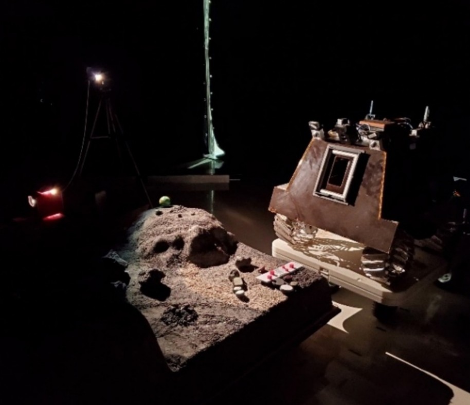
Figure 1. The lunar rover engineering model next to the LUSR target area.
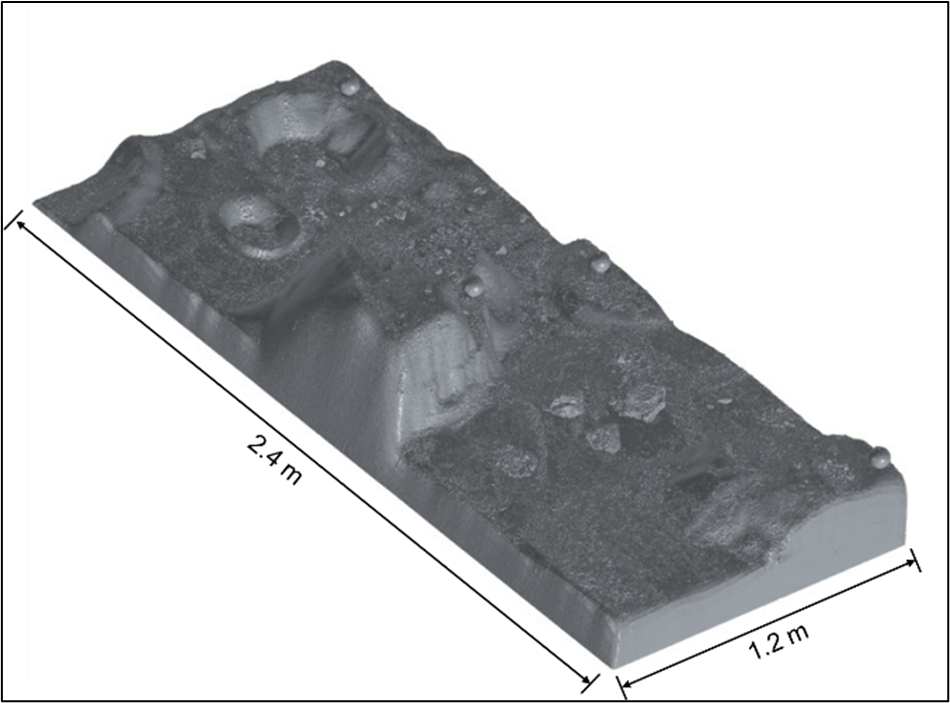
Figure 2. 3D mesh of the LUSR.
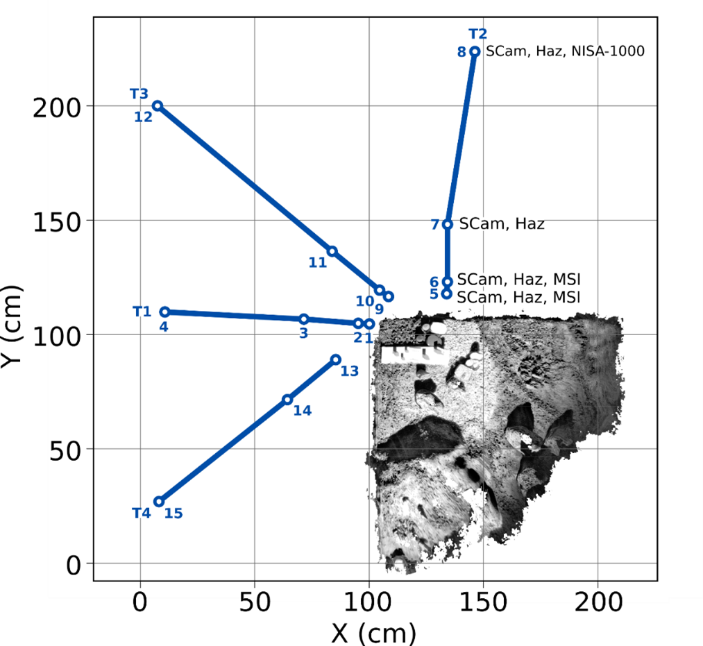
Figure 3. Transects T1-T4 and imaging stations 1 to 15, shown relative to the 3D point cloud of the target area. The imagers used at typical distances from the LUSR are indicated for T2.
Methods
All photogrammetric processing was conducted with the Ames Stereo Pipeline [4]. We first refined the geometric relationship between all cameras through a series of bundle adjustment passes constrained by a digital elevation model (DEM) and by uniformly distributed dense matches. A reference DEM made from StereoCam images was used to orthorectify all images and better constrain the feature matching and stereo correlation steps. Hazcam, MSI and NISA-1000 images were progressively included to the reconstructed scene using multiple “bundle_adjust” iterations. The 3D model was scaled using a set of control points from a handmade calibration target displayed at the center of the scene. We then used the “parallel_stereo” tool to generate a 3D point cloud from two MSI images taken at imaging stations 1 and 2, separated by 5 cm along a single radial transect (T1). For this, camera poses and dense matched features were derived from the previously calibrated camera rig.
We compared our photogrammetry-derived point clouds with a reference mesh of the LUSR made with the MetraScan (Creaform) metrological 3D scanner (see fig. 2). Distance statistics were derived from cloud to mesh (C2M) distances to evaluate each model’s accuracy.
Results
The calibrated camera 3D positions and orientations are shown in figure 4. Residuals of the triangulated features from the rig calibration 3D model are shown in figure 5, with a median reprojection error of 0.31 px, and RMS reprojection error of 0.47 px.
The point cloud resulting from the stereo process contains 9M features and median nominal point spacing of 44.3 μm. A 3D visualization of C2M distances between triangulated features and the LUSR mesh is shown in figure 6. We achieve a median absolute deviation of 173 μm (RMS of 387 μm) . For comparison, the median particle size of Apollo sample returned lunar soils is of 70 μm.
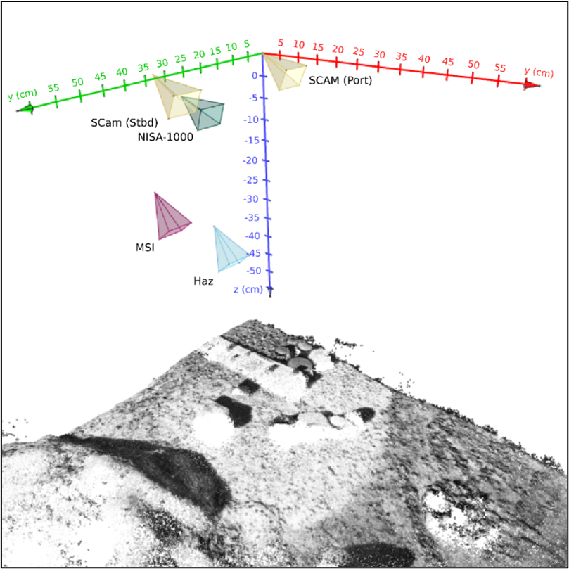
Figure 4. Calibrated camera positions and rotations relative to the triangulated point cloud resulting from the rig calibration process.
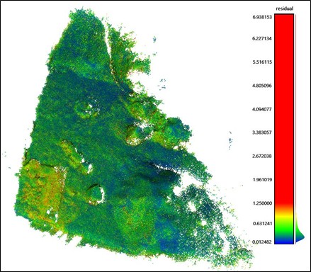
Figure 5. Residuals (pixels) for triangulated points from the rig calibration model.
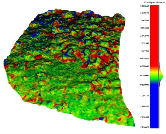
Figure 6. C2M distance (mm) between the stereo point cloud and the reference LUSR mesh.
Conclusion
The MSI can be used to generate point clouds with micrometric spatial resolution by collecting two images with overlap of a target separated by a 5 cm rover repositioning. Our approach relies on the complementarity of multiple instruments onboard the rover to scale the model and constrain the camera poses. In future work, we will evaluate the ability to constrain the MSI poses from a reduced image dataset collected at 1 or 2 imaging stations. We will also test benchmark convolutional neural network feature matching algorithms that may be more robust to the heterogeneous optical properties of our camera rig.
References
[1] Helfenstein and Shepard (1999), Icar 141, 107.
[2] Le Mouélic et al. (2020), Remote Sens. 12(11), 1900.
[3] Guo et al. (2021), Geophys. Res. Lett. 48, e2021GL094931.
[4] Beyer et al. (2018), Earth Space Sci. 5(9), 537-548.
How to cite: Diotte, F., Lemelin, M., A. Cloutis, E., Teti, F., Morisset, C.-E., Gingras, D., and Osinski, G.: Microscale 3D reconstruction of the lunar surface from constrained in situ robotic imaging, Europlanet Science Congress 2026, The Hague, The Netherlands, 7–11 Sep 2026, EPSC2026-713, https://doi.org/10.5194/epsc2026-713, 2026.


