
 3,1,1
3,1,1- 1National Institute of Astrophysics (INAF), Institute for Space Astrophysics and Planetology (IAPS), Rome, Italy
- 2Department of Physics, Tor Vergata University, Macroarea di Scienze MMFFNN, Rome, Italy
- 3Laboratory for Atmospheric and Space Physics (LASP), Boulder, CO 80303, USA
INTRODUCTION
The Emirates Mission to the Asteroid Belt (EMA) is an interplanetary mission to the Main Belt (1); during its journey the MBR Explorer Spacecraft will perform six fly-bys of primordial asteroids and planetary Gravity Assists targeting Venus, Earth and Mars before reaching asteroid 269 Justitia (2).
MIST-A is the Middle-Wave Infrared Imaging Spectrometer for Target Asteroids (3) aboard EMA. The instrument operates in the 2-5 𝜇m spectral range to study the asteroids’ surface composition and thermo-physical properties. MIST-A is composed of two units: the Optical Head (OH), which includes a telescope equipped with a scanning mirror and a spectrometer, and the Electronics Unit (EU). Mounted on the telescope’s entrance baffle is the Internal Calibration Unit (ICU), consisting of a diffuser and two IR emitters in front of which are placed polystyrene filters.
MIST-A is placed on the -Y side of the MBR with respect to the spacecraft’s Structural Reference Frame (SRF) as represented in Fig. 1. The instrument’s slit is aligned with the Z𝑆𝑅𝐹-axis and its boresight points along the -Y𝑆𝑅𝐹-axis, scanning in the X𝑆𝑅𝐹 direction. Its +Z-axis, towards which the instrument’s radiator is oriented, corresponds with +Z𝑆𝑅𝐹.
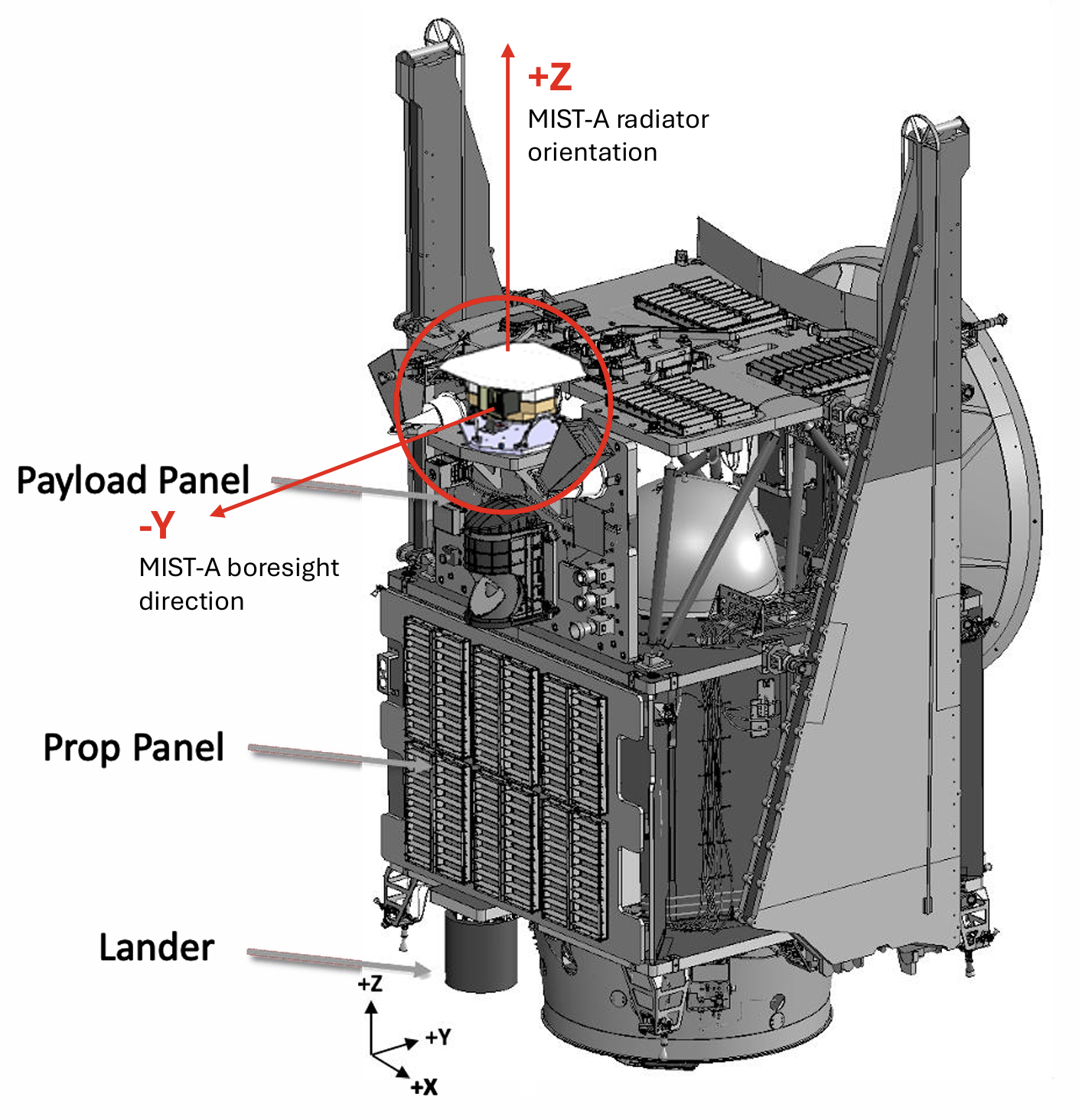
Fig. 1. MIST-A aboard the MBR Explorer.
MIST-A IN-FLIGHT CALIBRATION
MIST-A’s on-ground calibration campaign will be performed at INAF-IAPS and will cover the characterization of the instrument’s performances and the ICU. The instrument will also undergo in-flight calibrations that are necessary to verify its correct operation and identify any unexpected change or degradation. MIST-A’s first in-flight calibration will happen during EMA’s Early Operations Phase shortly after launch and it will consist of the Internal Calibration carried out through the ICU to study the instrument’s relative spectral, spatial and radiometric performances. MIST-A will also perform in-flight geometric and radiometric calibrations. The main objective of the geometric characterization is to check the boresight's stability and its alignment within the SRF. The radiometric calibration aims to check MIST-A’s responsivity to verify the accuracy of the calibration pipeline that converts the raw data recorded in Digital Numbers (DN) into physical units of spectral radiance (𝑊/m2/𝜇𝑚 · 𝑠𝑟). Both procedures demand the observation of a bright IR source satisfying a specific set of requirements. The geometric calibration requires a target with an angular size 𝛿 ≤ 238 𝜇rad and a phase angle 𝛼 ≤ 90°, while the radiometric needs a large body with 𝛿 ≥ 4.65 mrad and preferably a phase angle 𝛼 ≤ 45°. Planning of both characterizations also has to consider that during the measurements the Sun needs to be kept out of the instrument’s FOV, which provides a requirement on the Sun-Probe-(-Y𝑆𝑅𝐹-axis) angle 𝛾, corresponding to the boresight orientation, of 𝛾 ≥ 90°. Finally, thermal analyses have shown that a Sun Keep-Out-Zone (KOZ) has to be implemented in order to protect the spacecraft’s subsystems from damage due to Sun exposure; this dictates the constraints for the angle 𝜃 between the Sun-Probe vector and the +Z𝑆𝑅𝐹-axis (Fig. 2).

Fig. 2. Sun KOZ defined by the allowed values (in green) of the Sun-Probe-(+Z𝑆𝑅𝐹)-axis 𝜃 angle (deg) as a function of the Solar Distance (AU) of the spacecraft throughout the mission.
Through the development of a Python program, a study was performed for each proposed target of the calibrations to identify the time windows throughout EMA’s journey where all requirements would be met and observations could be performed. Possible targets for the geometric calibration have been identified in Jupiter, Mars, Arcturus and Antares, while for the radiometric calibration the preferred source is the Moon, although Earth, Mars and Venus are valid alternatives.
Data on the location of the spacecraft, the Moon and the planetary targets in the J2000 Sun-centered frame used for the mission have been inferred directly from EMA’s Trajectory file, which has been developed through the SPICE System (5). The stars coordinates have instead been deduced from their distance from the Solar System, their Right Ascension and Declination.
During the analysis the spacecraft’s orientation was fixed with the X𝑆𝑅𝐹-axis normal to the Sun-Target-Probe plane (Fig. 3), so that the Solar Arrays are kept normal to the Sun, in the most optimal power-positive angle. This configuration is ideal but also the most restrictive, and in case no compatible targets are found it can be modified.
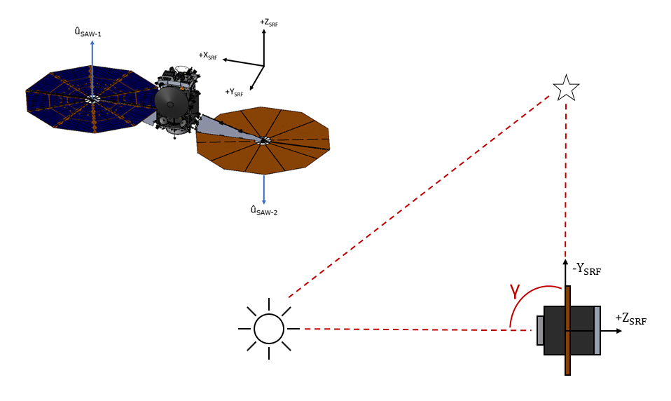
Fig. 3. Orientation of the spacecraft with respect to the Sun-Target-Probe plane during MIST-A’s in-flight calibration measurements.
RESULTS OF THE TARGET SELECTION
Through an ordered analysis that evaluated the compliance to each observation constraint for every proposed target, we found the indicative time windows inside which all requirements would be met thus allowing to perform the calibration with that specific body. These were then compared with the time marks defined for the fly-bys, the gravitational assists and the nine cruise phases performed during the mission.
Tables in Fig. 4 show the results of the target selection study.

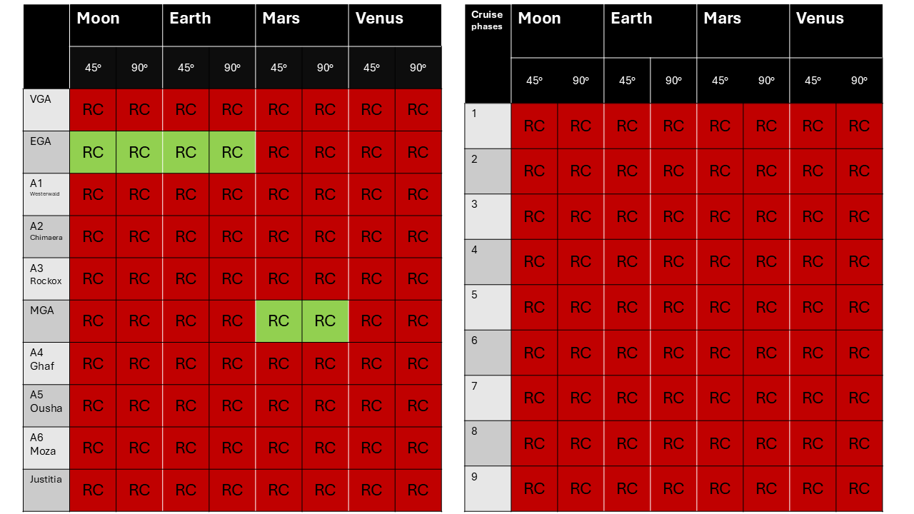
Fig. 4. Results of the target selection for the geometric (top) and radiometric (bottom) calibration, analyzing the available windows at fly-bys and gravity assists (left tables) and during cruise stages (right tables). The green cells point the windows where requirements are met and calibrations can be performed. For the radiometric two cases for the phase angle were considered: the preferable but more restrictive requirement of 𝛼 ≤ 45° and 𝛼 ≤ 90° as a second option.
The study confirmed that both stars can be used as targets for the geometric calibration, as well as Jupiter and Mars. The results of the analysis for the radiometric calibration indicate fewer opportunities, although they show that it should be possible to perform the characterization in two different stages and that the Moon is a viable target, as preferred. Additionally, this study was performed considering particularly constrictive requirements, which may be softened if multiple iterations of the calibrations are needed.
REFERENCES
1. Al-Mazmi et al., ,” AGU, , no. id. P44B-01, 2023.
2. Al-Mazmi et al., ,” COSPAR, , no. b1.1-0036, July 2024.
3. Raponi A., Filacchione G. et al., 2023, LPICo, 2851, 2450.
4. NASA NAIF, https://naif.jpl.nasa.gov/naif/spiceconcept.
How to cite: Cencia, C., Redick, R., Alblooshi, H., Pilinski, E., Reed, H., Villa, J., Lamprecht, B., Filacchione, G., and Ciarniello, M.: Target Selection for In-Flight Calibrations of the MIST-A Instrument, Europlanet Science Congress 2026, The Hague, The Netherlands, 7–11 Sep 2026, EPSC2026-986, https://doi.org/10.5194/epsc2026-986, 2026.


